
Stepper motors remain one of the most widely deployed motion technologies in industrial automation systems due to their predictable positioning behavior, simple open-loop architecture, and cost-effective integration into OEM machinery.
Why Stepper Motors Are the Backbone of Industrial Automation
Walk through the engineering floor of almost any OEM machine manufacturer — packaging lines, benchtop CNC routers, solar tracking arrays, laboratory automation systems — and you'll find stepper motors running quietly in the background. Despite decades of servo motor improvements, stepper technology hasn't been displaced. If anything, it's grown more embedded in the fabric of industrial machine design.
The core reason is straightforward: open-loop positioning works reliably for a very large class of industrial applications. When a machine doesn't require real-time torque feedback or continuous high-speed operation, adding a servo encoder, drive tuning, and closed-loop commissioning overhead creates cost and complexity that isn't justified. A well-sized stepper motor with a quality driver will index a linear axis, rotate a rotary table, or feed material through a mechanism with consistent, repeatable results — no tuning required, no feedback loop to commission, no encoder cable to maintain.
Pulse-and-direction control means the motion controller sends step pulses; the motor follows. Sequence the steps correctly, respect the torque-speed curve, and you get reliable positioning. For OEM machine builders especially, this predictability has real value: the same motor, same driver, same motion parameters across a production run of 200 machines delivers consistent field performance without per-unit calibration.
Cost matters at scale. A NEMA 23 hybrid stepper with a 2-phase bipolar driver often costs a fraction of an equivalent servo system. When a machine has four or six axes performing relatively modest positioning tasks, the bill-of-materials difference is significant. Stepper motors also carry inherent holding torque — they resist position disturbance at rest with no active velocity command. That's useful for clamping mechanisms, Z-axis vertical holds, and any application where the motor needs to lock a load without consuming continuous full holding current, when using idle current reduction features on modern drivers.
Reliability in industrial environments is another factor. Hybrid stepper motors — the dominant type in industrial automation — have no brushes, limited wear components, and can survive substantial shock and vibration loads depending on construction. Modern sealed or IP-rated variants handle coolant mist, dust, and moderate humidity without special accommodation. For engineers designing equipment destined for factory floors rather than laboratory benches, that matters considerably.
That said, stepper motors aren't always the right answer. High-speed continuous duty, sub-micron closed-loop positioning, and dynamic load following are domains where servo systems earn their price premium. Understanding where stepper motors fit — and where they don't — is practical knowledge that separates experienced motion system designers from engineers who over-specify every axis with servo hardware. For a deeper look at how these motors function at a physics level, the HDBMotor technical guide on how stepper motors work covers the magnetic circuit and commutation sequence in detail.
7 Industrial Application Areas Where Stepper Motors Dominate
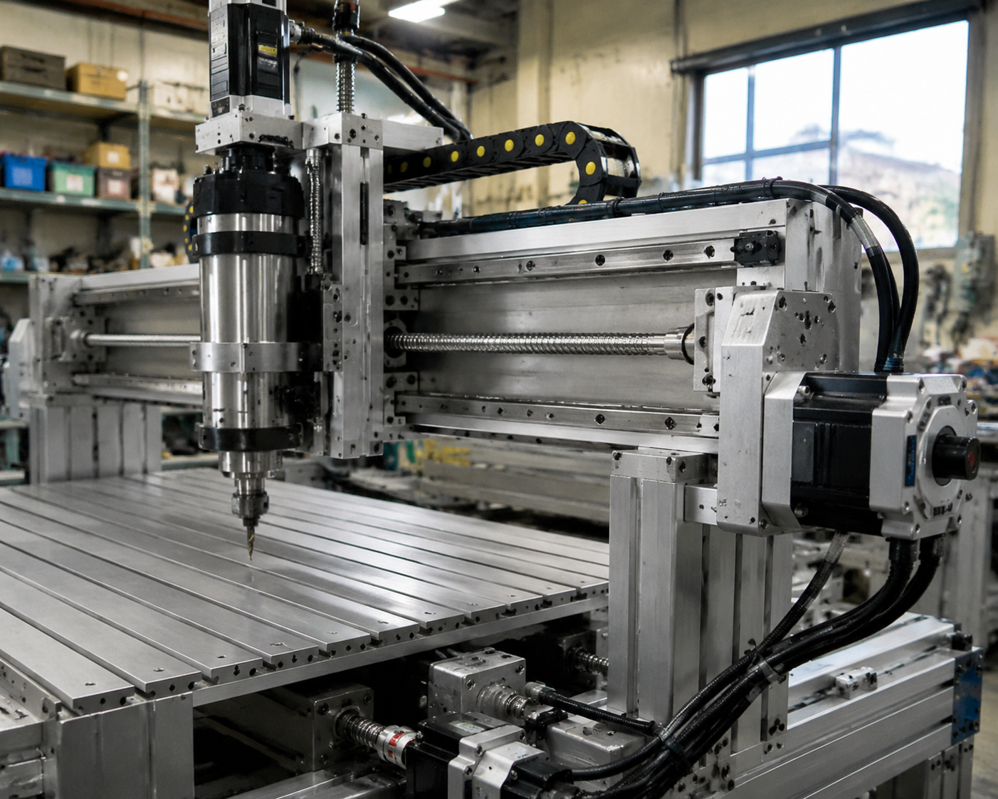
CNC Machines and Routing Systems
CNC routing is arguably where stepper motors built their reputation in light industrial automation. Gantry-style CNC routers — used for wood, aluminum, plastic, and composite cutting in small-to-mid production environments — routinely rely on NEMA 23 or NEMA 34 hybrid steppers on X, Y, and Z axes. The positioning requirement here isn't exotic: with 1/8 or 1/16 microstepping and a typical ballscrew pitch of 5mm, you can achieve sub-0.1mm repeatability that satisfies most routing applications.
Microstepping deserves attention here. Reducing step angle via microstepping — from the native 1.8° full step down to 0.1125° at 1/16 — doesn't linearly improve accuracy the way many engineers assume. What microstepping genuinely does is smooth motion and reduce resonance at mid-speed operation, which has real practical value on gantry systems where resonance can leave visible surface marks in cut material. For step angle selection considerations, the step angle explained guide covers resolution versus accuracy tradeoffs in practical terms.
Axis synchronization on dual-motor gantry configurations requires careful attention. Running two motors on a shared mechanical axis — common on wide-format routers — requires matched motor specifications and identical driver parameters. Any torque imbalance or step loss differential between the two motors will rack the gantry over time. Some OEMs address this with periodic homing routines; others use closed-loop steppers with encoders to detect and correct accumulated error before it becomes a machine fault.
Holding torque is particularly important on the Z axis of a CNC router or mill. When a spindle is plunging or the machine pauses mid-operation, the motor must hold vertical position against both tool force and gravity. Undersized holding torque here translates directly to lost Z-depth control — a problem that often surfaces as inconsistent cut depth across a production run rather than as an obvious motor fault.
Desktop CNC differs from industrial CNC in one critical dimension: duty cycle. A hobbyist router running intermittently is very different from a production router running 16-hour shifts. Thermal management — motor frame temperature, driver heat dissipation, ambient enclosure temperature — becomes a design factor that must be addressed with engineering margin, not optimistic assumptions. The complete stepper motor technical guide covers thermal considerations in the context of continuous duty operation.
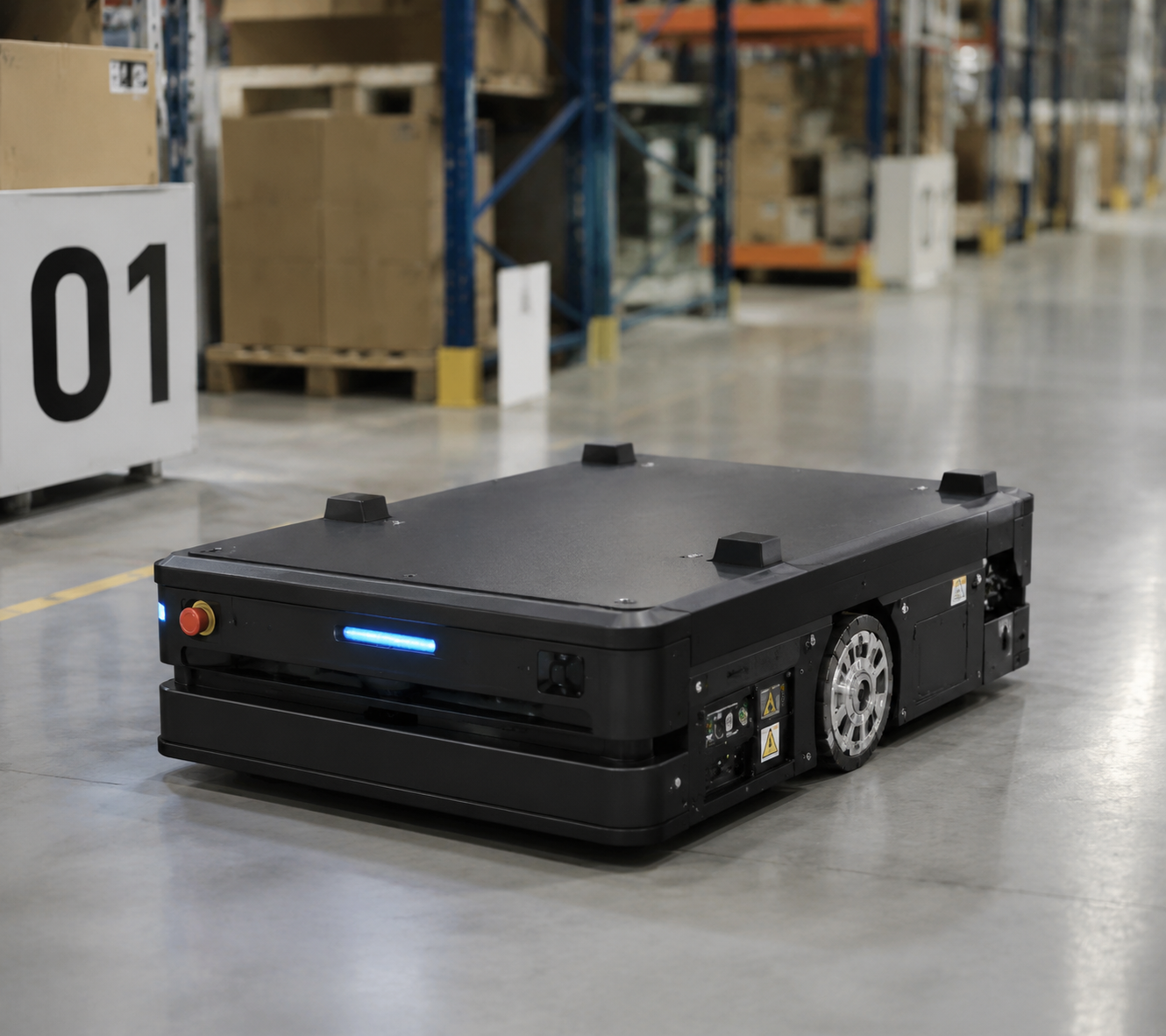
AGV and Mobile Robot Drive Systems
Automated guided vehicles and autonomous mobile robots operating in warehouse or factory environments represent an interesting stepper motor application because the requirements are somewhat unusual: low-to-medium speed, high starting torque, compact drive packaging, and battery-efficient operation.
Stepper motors generate maximum torque at or near stall — the exact operating point where an AGV wheel drive needs to overcome static friction, ramp grades, and cargo inertia during acceleration from rest. This torque characteristic is well-matched to the application, particularly for lighter AGVs carrying loads up to a few hundred kilograms at walking speeds of 0.5–1.5 m/s.
Gearbox integration is standard practice in AGV drive systems. A planetary gearbox with ratios between 10:1 and 30:1 combined with a NEMA 24 or NEMA 34 stepper produces a compact, high-torque wheel drive that can be packaged tightly inside the robot chassis. The gear reduction also moves the motor's operating speed into the upper-efficiency band of its torque curve, improving battery consumption relative to a direct-drive configuration.
Navigation precision is where open-loop stepper control has inherent limits. Differential-drive AGVs using odometry for position estimation accumulate error over distance, and stepper step loss under load spikes degrades odometry accuracy. In practice, most modern AGV systems use SLAM lidar or magnetic floor guidance as the primary navigation reference, with wheel encoders or stepper step counts providing supplementary short-distance motion feedback. The motor doesn't need to be the source of centimeter-level positioning accuracy; the navigation system handles that.
Current regulation in the driver is critical for battery-powered applications. Modern stepper drivers operating in constant-current mode with idle current reduction — typically 50% of run current at standstill — significantly reduce average power draw. That's meaningful when a vehicle has 30+ hours of required runtime between charging cycles and every milliamp-hour of battery capacity has a weight and cost implication.
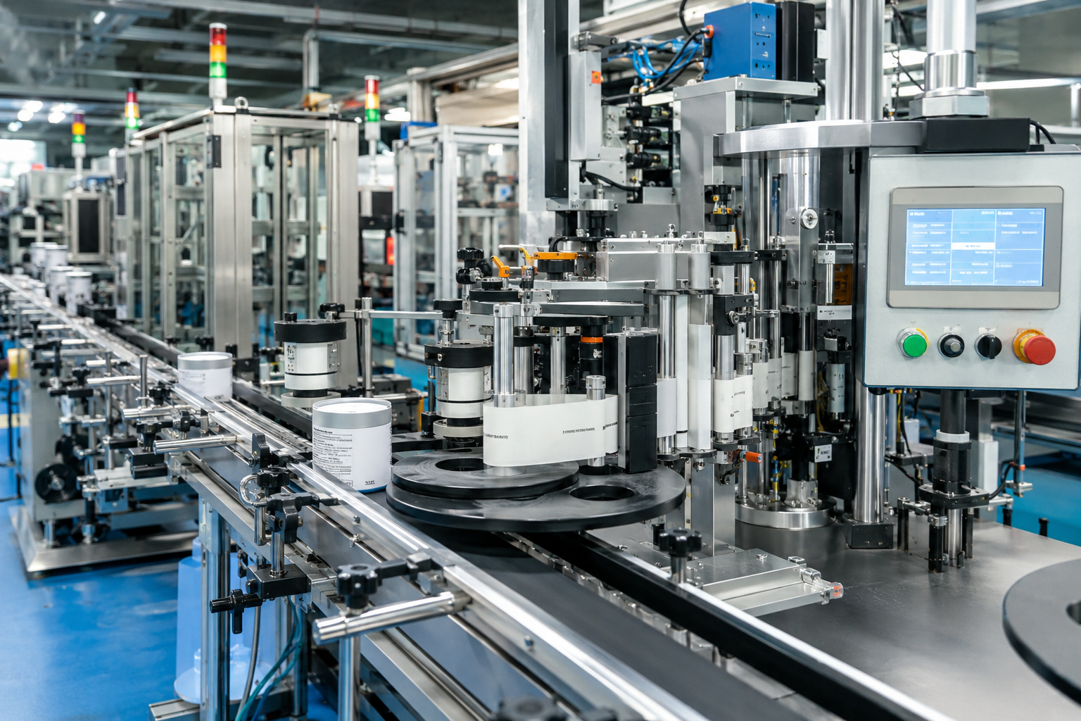
Packaging and Labeling Machinery
Packaging machinery is a natural fit for stepper motors. The core motion requirements — index a fixed distance, repeat accurately tens of millions of times per year, synchronize with upstream and downstream conveyor sections — map directly to what steppers do well.
Label applicators, for example, require dispensing a precisely metered length of label stock synchronized to product flow on the main conveyor. A stepper motor driving the peel plate or take-up roller advances an exact number of steps per product pitch, triggered by a product sensor. No velocity feedback required. The motion is deterministic and repeatable, which is exactly the characteristic that makes these machines easy to commission and reliable in production.
Form-fill-seal machines are more demanding. The bag film must be indexed accurately to maintain consistent seal position, and the motor may need to handle varying web tension as roll diameter decreases. In these cases, running a closed-loop stepper with encoder feedback is worth considering, particularly when label registration tolerance is tight — under ±0.5mm.
Vibration control is a real engineering concern on packaging lines running at high cycle rates. Tens of millions of indexing cycles per year amplifies any resonance tendencies in the motor-load system. Switching from full-step to 1/8 microstepping, selecting a 5-phase stepper instead of 2-phase, or adding mechanical damping through compliant couplings can meaningfully reduce vibration signature and extend mechanical life of the driven components.
Thermal loading is a consideration packaging engineers sometimes overlook during initial machine design. A motor that runs comfortably at rated current during lab testing may run hot when the machine operates in a heated sealing zone with limited air circulation. Designing with a minimum 20°C thermal margin relative to worst-case ambient conditions is a practical minimum, not a conservative luxury.
Solar Tracking Systems
Single-axis and dual-axis solar trackers move slowly — sometimes as little as a few degrees per hour — but they do it continuously, outdoors, in demanding environmental conditions, for operational lifetimes measured in decades. The motion requirements are modest by industrial standards: slow, smooth angular repositioning of a panel array that might weigh several hundred kilograms.
What makes this application technically interesting is the combination of very low speed, high load inertia, and outdoor environment. A stepper motor driving through a high-ratio worm gearbox or planetary gearbox will hold panel position against wind loads without continuous current draw — the irreversibility of a worm drive combined with stepper holding torque provides inherent position locking. That's a system-level efficiency advantage over servo-driven trackers that must actively command position hold.
Gearbox selection critically affects long-term tracker performance. The gearbox sees cyclic loading from wind gusts, thermal expansion stress, and constant slow-speed input. Backlash in the gearbox directly translates to panel positioning error, which accumulates as a collection performance ratio (CPR) loss throughout the day. Low-backlash planetary gearboxes — arc-minute class — are preferred where tracking accuracy must be better than ±0.5°.
Motor weatherization requirements are non-negotiable. IP65 or IP67 rated motors with sealed connector entries, UV-resistant cable jacketing, and corrosion-resistant shaft coatings should be specified as standard. Condensation ingress is a leading failure mode in outdoor motor applications; even IP65-rated motors benefit from drain hole orientation being considered during mechanical installation design.
In off-grid or battery-backed tracker installations, power efficiency matters considerably. Sizing the motor to run at 60–70% of rated current during normal repositioning — reserving current headroom for high-load wind-induced displacement correction — extends motor and driver thermal life substantially in high-ambient-temperature deployment regions.

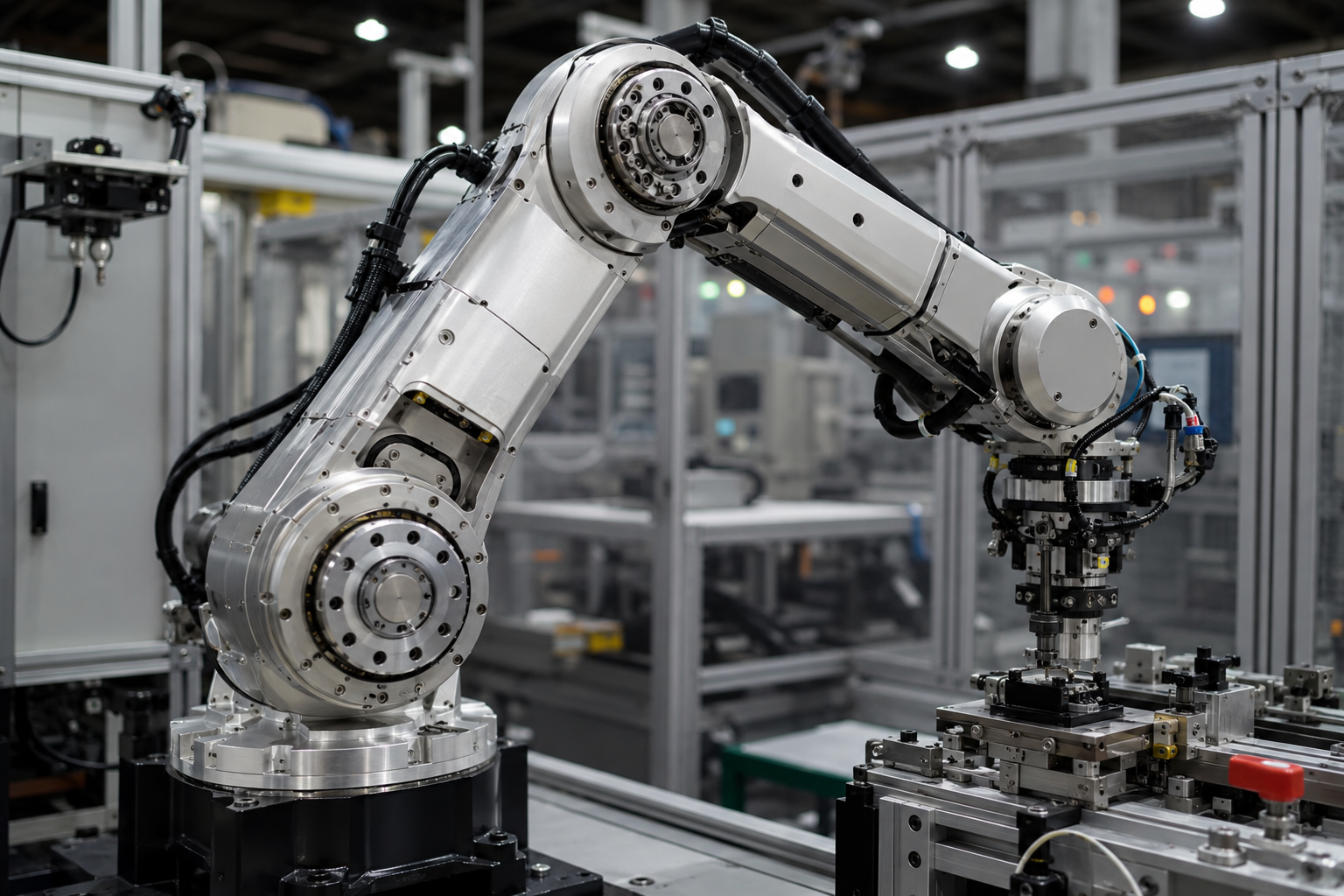
Industrial Robotics and Robotic Arm Joints
Light-to-medium duty robotic arms — SCARA robots, small collaborative robots, delta robots for pick-and-place — commonly use stepper motors with harmonic or planetary gearboxes at the wrist, elbow, and shoulder joints. The positioning repeatability of a quality hybrid stepper (±0.09° native step angle) combined with a 50:1 or 100:1 harmonic drive reduction yields joint-level repeatability well under 0.1mm at the tool tip for arm lengths under 500mm.
Resonance management is non-trivial in robotic arm joints. The motor-gearbox-arm combination is a spring-mass system, and exciting its natural frequency during acceleration or deceleration produces arm vibration that can persist for hundreds of milliseconds — unacceptable in high-speed pick-and-place operations. S-curve acceleration profiles, careful current tuning, and damping provisions in the motion controller significantly reduce settling time. Getting this right during machine design — not during field commissioning — is the difference between a robot that cycles cleanly and one that needs constant motion parameter adjustment.
Compact motor sizing is a constraint driven by robot link geometry. Joint motors in SCARA or articulated arms must fit within the mechanical envelope of the arm structure. Hollow-shaft stepper motors with through-bore designs allow cable and pneumatic routing through the joint — an important packaging consideration that influences arm design freedom significantly on multi-joint configurations.
For collaborative robots operating near human workers, current limiting features in modern stepper drivers provide a basic layer of force restriction. This isn't equivalent to the full dynamic torque control of a servo system, but for low-speed collaborative manipulation tasks at light payload ratings, it can satisfy safety requirements at meaningfully lower system cost.
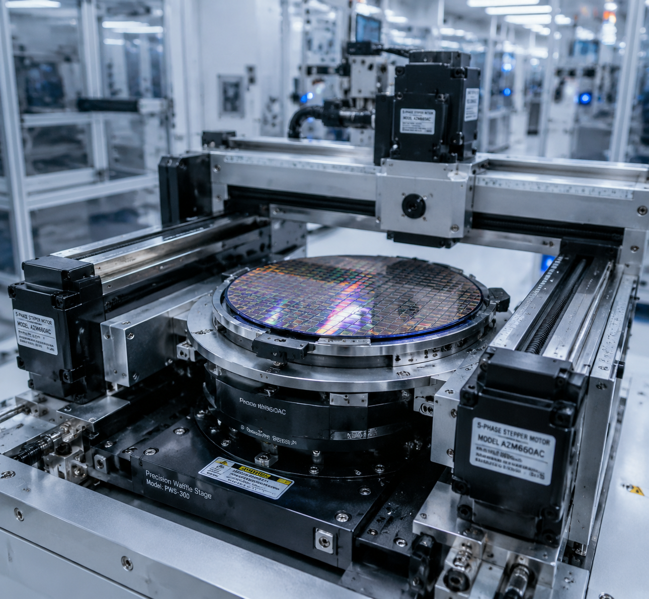
Semiconductor Equipment
Semiconductor manufacturing automation operates at the demanding end of what stepper motors can accomplish. Wafer handling systems, mask aligners, inspection stage systems, and die bonding equipment all require motion that is smooth, low-vibration, thermally stable, and repeatable at micrometer-level scales.
In these applications, the vibration footprint of the motor is as important as its positioning accuracy. Each motor current commutation event produces a torque ripple impulse that propagates through the machine structure. On a precision wafer stage, this manifests as image blur in inspection systems or die placement error in bonding equipment. This is one application where 5-phase stepper motors offer a genuine technical advantage over 2-phase designs — 10 steps per electrical cycle versus 4 generates dramatically lower torque ripple and finer native resolution at full-step operation. The 2-phase vs 3-phase vs 5-phase stepper motor comparison covers this tradeoff with engineering depth.
Thermal stability affects positioning repeatability. Motor winding temperature affects winding resistance, which in a constant-voltage driver affects phase current — and therefore holding torque and position stiffness. In constant-current driver designs, this effect is largely compensated. This is one reason why current-regulated drivers should be the default specification in any application where thermal drift of positioning accuracy is a concern.
Cleanroom environments add requirements beyond standard industrial specifications. Outgassing from motor materials, lubricant vapor from bearing grease, and particulate generation must comply with cleanroom classification requirements. Stepper motors specified with vacuum-compatible lubricants and certified low-outgassing materials are available from manufacturers serving this segment — but must be explicitly specified at procurement, not assumed from a standard catalog part.
Fine microstepping at 1/64 or finer resolution is common in semiconductor stage drives. At these resolutions, the linearity of the microstepping response becomes relevant — motor magnetic circuit quality, driver current DAC resolution, and matched phase resistance all influence whether commanded micro-positions correspond to actual physical positions. Engineers selecting motors for semiconductor applications should request microstepping linearity test data, not rely solely on rated resolution specifications.
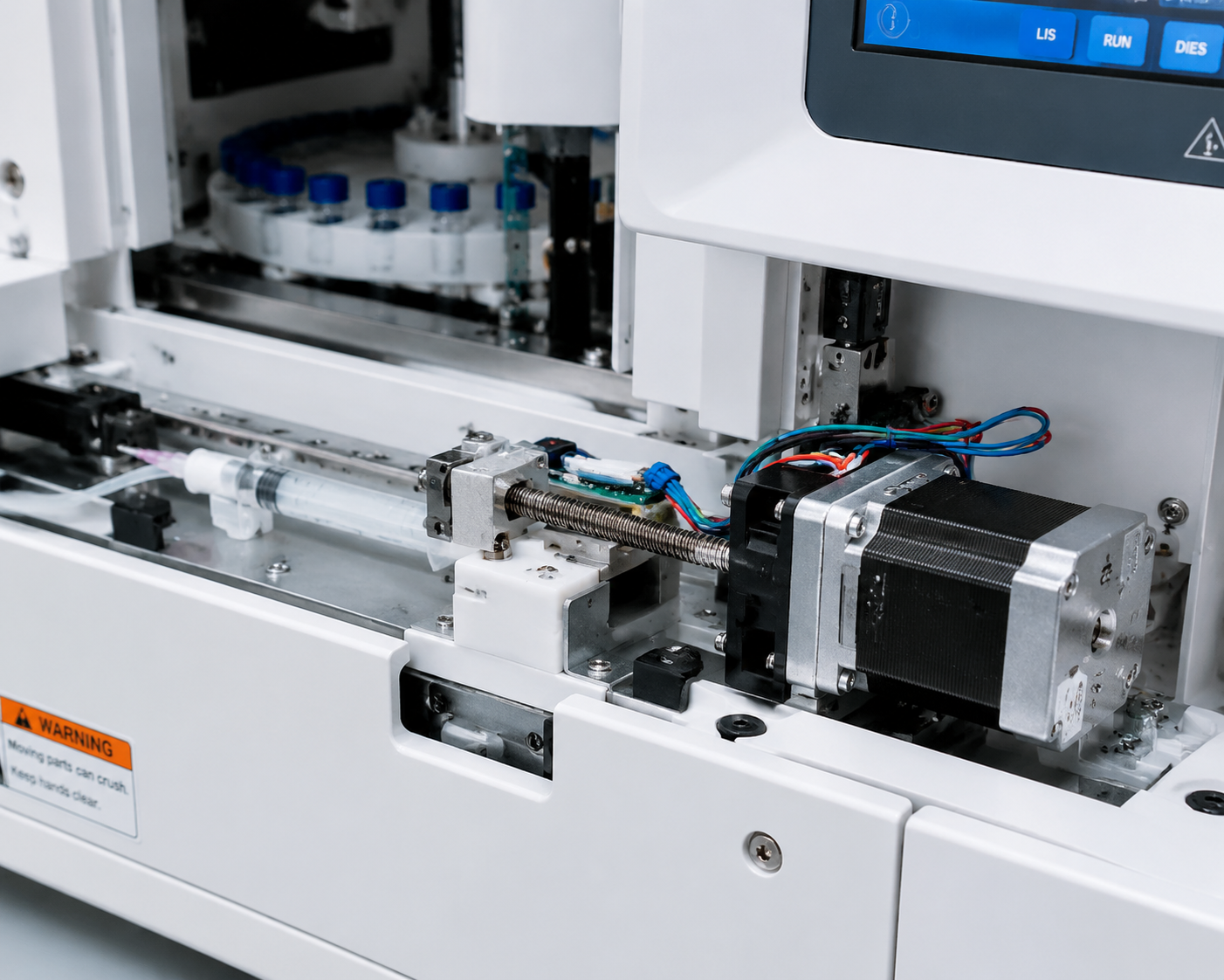
Medical Device Automation
Medical automation involves overlapping requirements: compact form factor, smooth low-speed motion, low acoustic noise, and materials compatible with regulatory documentation. Stepper motors appear extensively in infusion pumps, diagnostic analyzer sample handling, laboratory liquid handling systems, ophthalmic instruments, and rehabilitation equipment actuators.
In peristaltic pump and syringe pump mechanisms, the smoothness of motor rotation at low speeds directly affects fluid delivery accuracy. A 2-phase stepper at 10 RPM in full-step mode produces torque pulsations that translate to flow rate variation — measurable and clinically relevant in infusion applications. Running in 1/16 or 1/32 microstepping eliminates most of this variation, producing near-smooth rotation at therapeutically relevant flow rates. Resonance near the natural frequency of the pump mechanism — typically in the 50–200 Hz step rate range — must be characterized early in development and addressed through motion profile design or current damping tuning.
Laboratory analyzers and automated sample handling systems place a premium on positional repeatability across temperature cycles. Sample carousels and dispensing heads operating in temperature-controlled laboratory environments see thermal gradients from 4°C refrigerated sample zones to ambient instrument housings. Motor specification should account for the full operating temperature range, and gearbox lubricant viscosity change at the lower temperature extreme must be factored into the torque budget — not assumed constant from room-temperature test data.
Acoustic noise matters more in medical applications than in most industrial contexts. Instruments operating in clinical or laboratory settings near personnel have noise expectations that simply don't apply on a factory floor. 5-phase stepper motors are advantageous here — their lower torque ripple and smoother commutation sequence translate directly to lower acoustic output at operating speeds. Vibration isolation mounts between motor and instrument chassis further reduce noise transmission to the outer housing.
How to Select the Right Stepper Motor for Your Application
Motor selection done rigorously starts with the load, not the motor catalog. Derive torque and speed requirements from the mechanical system first, then find a motor that meets them with appropriate margin.
Calculate required shaft torque. Sum all contributors: friction, inertia during acceleration, gravity on vertical axes, and process loads. Apply a service factor — typically 1.5× to 2× for industrial applications — to account for real-world variation and component wear over service life.
Determine maximum operating speed. Identify the step rate corresponding to maximum commanded velocity. Check the motor's published torque-speed curve at the intended driver voltage to confirm adequate torque margin at that speed — not just at stall.
Evaluate inertia matching. Load inertia reflected to the motor shaft should ideally fall within 1:1 to 10:1 of the motor rotor inertia. Exceeding this ratio degrades dynamic response and increases step loss risk under rapid acceleration. A gearbox reduction can improve the inertia ratio while also multiplying available torque.
Select driver voltage. Higher bus voltage extends usable speed range by overcoming back-EMF at higher step rates. A motor with 3.0V rated winding voltage can be driven at 24V, 36V, or 48V DC with a current-regulated driver — the higher voltage provides faster current rise time per step, preserving torque at speed.
Account for thermal environment. Derate motor rated current by 10–20% in enclosed, low-airflow environments. Verify that motor case temperature — typically limited to 80–90°C surface — will remain within bounds at application duty cycle and worst-case ambient temperature.
Consider encoder addition for critical axes. Closed-loop stepper systems with encoder feedback and stall detection can recover from step loss events rather than propagating positioning error. For high-value workpieces or safety-critical positioning axes, this is often worth the incremental system cost.
For construction-level context that informs selection decisions, the types of stepper motors guide and the hybrid vs PM stepper motor comparison explain why hybrid stepper motors dominate industrial applications.
| Selection Parameter | Light-Duty Systems (Medical, Lab Automation, Packaging) | Medium-Duty Systems (CNC, AGV, Robotics) | Heavy-Duty Systems (Solar Tracking, Industrial Gantry) |
|---|---|---|---|
| Typical Motor Frame | NEMA 17 / NEMA 23 | NEMA 23 / NEMA 24 | NEMA 34 / NEMA 42 |
| Typical Holding Torque | 0.1 – 1.0 N·m | 1.0 – 4.5 N·m | 4.5 – 12+ N·m |
| Recommended Driver Voltage | 12 – 24V DC | 24 – 48V DC | 48 – 80V DC |
| Gearbox Requirement | Usually not required | Depends on inertia and torque demand | Typically required for torque multiplication |
| Encoder Feedback | Optional | Recommended for critical positioning axes | Strongly recommended |
| Typical Microstepping Setting | 1/8 – 1/32 | 1/4 – 1/16 | 1/2 – 1/8 |
| Thermal Derating Factor (High Ambient / Enclosed Cabinet) | 0.85 | 0.80 | 0.75 |
| Recommended Load-to-Rotor Inertia Ratio | ≤ 5:1 | ≤ 10:1 | Use gearbox reduction whenever possible |
| Primary Engineering Focus | Compact size, smooth low-speed motion, low noise | Balanced torque, speed, and positioning stability | High torque reserve, thermal stability, long-term durability |
| Typical Duty Cycle | Intermittent to moderate continuous duty | Continuous industrial operation | Heavy continuous-duty operation |
Common Engineering Mistakes in Stepper Motor Applications
Most stepper motor field failures trace back to a small number of recurring engineering decisions made during machine design — not to manufacturing defects. These are the mistakes that show up repeatedly across different applications and industries.
Undersized or mismatched drivers. A motor rated for 3A per phase running on a driver set to 2A loses torque capability across the speed range and may lose steps under load. Conversely, a driver set significantly above the motor's rated current will overheat the winding. Using a 24V driver on a system that needs 48V to maintain torque at operating speed is a common cause of sluggish high-speed performance that gets misdiagnosed as a motor problem — but is really a driver selection issue.
Ignoring mid-range resonance. Stepper motors have a natural resonance frequency — typically in the 100–300 Hz step rate range for common NEMA 23 motors — where the rotor's spring-mass response causes rough operation and potential step loss. Engineers who ramp motor speed through this band without mitigation will encounter intermittent position errors that are difficult to reproduce and diagnose. Solutions include acceleration profiles that move through the resonance band quickly, driver anti-resonance algorithms, or choosing a 5-phase motor whose finer step angle reduces the resonance signature at equivalent mechanical speeds.
Using holding torque as the design torque figure. It's the most visible number in a motor datasheet, but it's the torque at zero speed. Available torque at the step rate corresponding to actual operating velocity is the relevant figure for dynamic applications, and it can be substantially lower. Pull-out torque and pull-in torque are different values from holding torque; the stepper motor torque curve guide explains the distinction in engineering context.
Thermal overload in cyclic applications. Continuous current drive mode — necessary for holding torque on loaded axes — generates constant winding heat even at zero velocity. In machines with high on-time duty cycles running in warm industrial environments, winding temperature can exceed rated limits even when the motor appears lightly loaded by torque requirements. Idle current reduction, proper sizing with thermal margin, and enclosure ventilation assessment belong in the initial design review, not the field
Discussing a Motion System Requirement?
Selecting a stepper motor for industrial automation is rarely just about holding torque. Load inertia, acceleration profile, gearbox backlash, thermal limits, resonance behavior, and driver voltage all influence real-world machine performance.
For OEM equipment manufacturers developing CNC systems, robotics, packaging machinery, solar tracking systems, or laboratory automation equipment, HDBMotor provides application-focused engineering support for motor sizing, gearbox matching, and driver selection.
If you are evaluating a motion system for a new machine platform or upgrading an existing design, our engineering team can help review torque requirements, operating speed ranges, and positioning objectives.