
Most engineers don't start looking at planetary gearboxes because they want to. They start looking because something went wrong — a stepper stalled under load, a positioning axis vibrated itself out of tolerance, or a motor ran so hot it triggered thermal shutdown at 40% of rated speed. The planetary gearbox exists to fix exactly these failure modes, and once you understand why, it becomes hard to spec a demanding motion system without one.
This guide covers the mechanics, the selection logic, where these assemblies work best in production environments, and what to watch for when sourcing from a manufacturer. It's written for engineers who need to make a decision, not for people who want to read about gears.
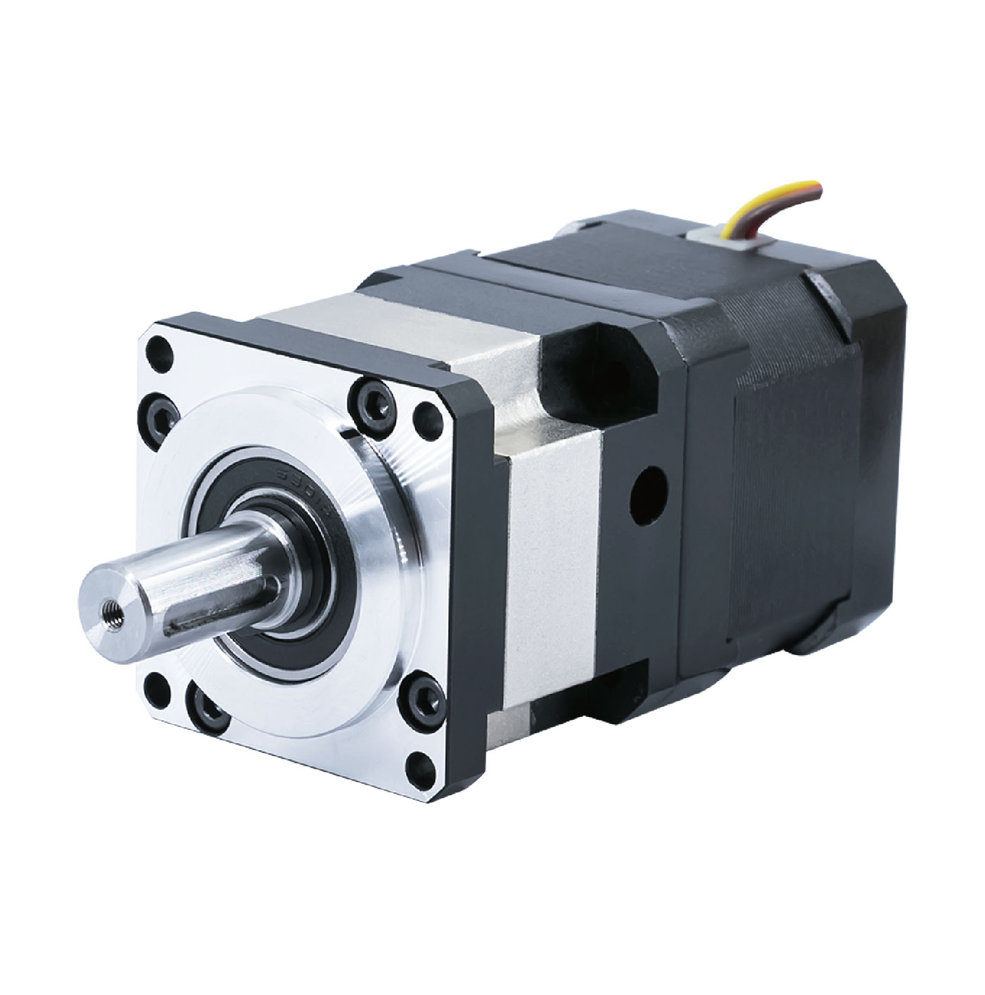
What a Planetary Gearbox Actually Does to a Stepper System
A stepper motor moves in fixed angular increments. That's its strength — predictable, repeatable positioning without feedback. The problem is the torque curve. Peak torque occurs at zero speed and drops sharply as RPM climbs. Run a stepper at 800 RPM and you're often working with 30–40% of the rated holding torque. Push it through the 100–300 RPM resonance band and the motor vibrates, sometimes severely enough to lose steps entirely.
A planetary gearbox changes the operating point. The motor runs fast — 500 to 1500 RPM at the input — while the output shaft turns slowly with multiplied torque. A 20:1 ratio delivers 20 times the input torque at the output (minus efficiency losses, typically 5–10% per stage). The motor stays in its efficient RPM range, above resonance, and the reflected inertia of the load drops by the square of the ratio. A load that appeared as 100 kg·cm² to the motor shaft now looks like 1 kg·cm². That change alone dramatically improves how quickly and cleanly the motor can accelerate and stop.
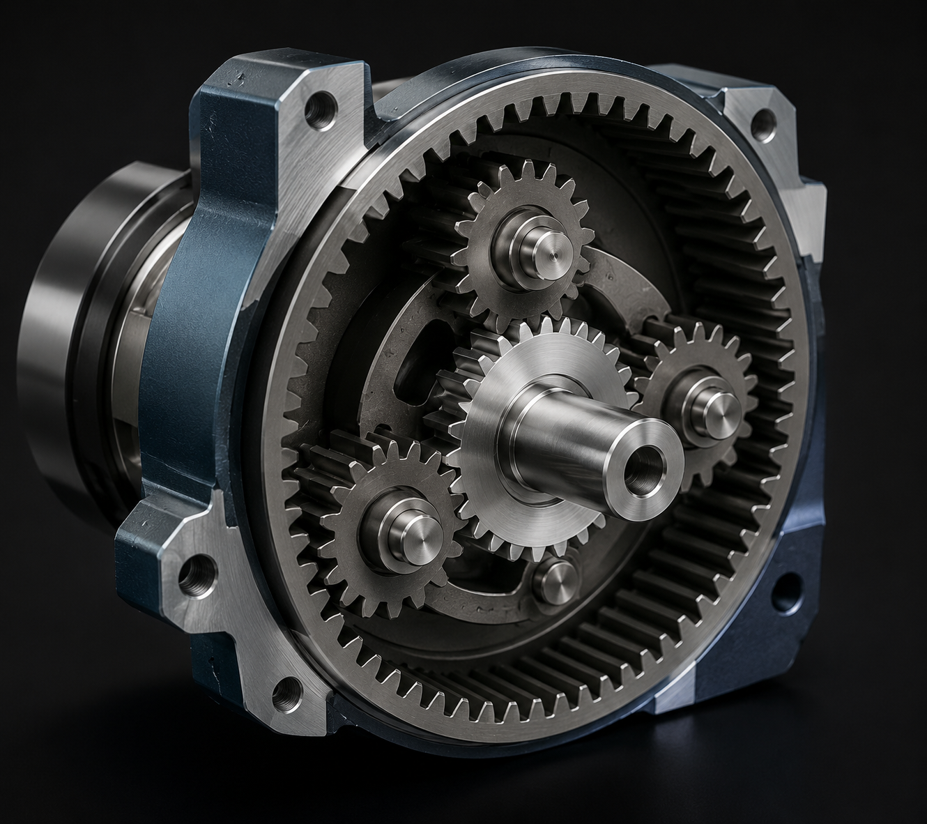
The planetary architecture — sun gear at the center, three or more planet gears orbiting outward, outer ring gear fixed — distributes load across multiple mesh points simultaneously. That's why planetary stages reach 90–97% efficiency while worm gearboxes at the same ratio struggle past 70%. It also explains why planetary units last longer under cyclic loading: no single gear tooth takes the full impact.
If your application also involves brushless DC motors rather than steppers, the same planetary reduction principle applies. HDB Motors produces Planetary Reduction Brushless Motors for higher-speed, continuous-duty configurations where BLDC characteristics are a better fit.
Where These Assemblies Actually Get Used
For a detailed breakdown of application categories with torque and speed reference data, see the Gearbox Stepper Motor Manufacturer Guide covering AGV, robotics, medical, and industrial automation use cases.
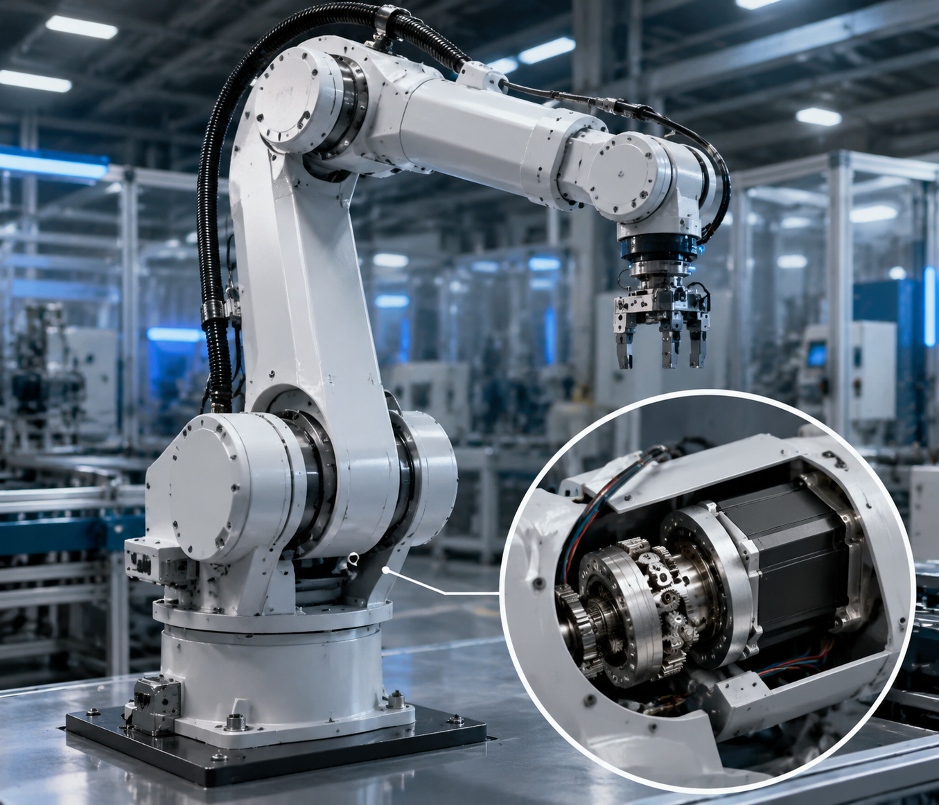
Robotic joints are probably the most demanding application. A 400 mm arm segment carrying a 2 kg payload generates significant torque at the shoulder joint, particularly during fast direction reversals. A NEMA 23 stepper through a 50:1 helical planetary stage handles this — but the key isn't just the torque number, it's the backlash. If the gearbox has 30 arcmin of play, a 400 mm arm drifts nearly 3.5 mm at the end effector just from mechanical slop. That's why precision robot joints use helical planetary stages with backlash at or below 5 arcmin.
Solar tracking systems are the opposite problem: very slow output, very high holding torque, and the motor runs continuously for years. A single-axis tracker might rotate 180° over 12 hours — roughly 0.004 RPM at the output shaft. At a 100:1 ratio the stepper input runs at 0.4 RPM, which is still almost stationary, but the key point is that the gearbox absorbs wind loading across its gear mesh rather than forcing the motor to hold position alone. Stepper motors hold position without power to the encoder — there's no position loss during brief power interruptions — which matters in outdoor installations where grid stability isn't guaranteed.
AGV steering axes, CNC rotary tables, peristaltic pumps, lab automation sample handlers, and lead-screw linear actuators all follow similar logic: the application demands torque and precision that a bare stepper can't reliably deliver, and a planetary stage resolves both at the same time.
Picking the Right Gear Ratio
The ratio selection process sounds mechanical but it's where most system-level problems actually originate. Get it wrong and you'll either burn out the motor trying to move a mismatched inertia load, or you'll over-reduce and lose the speed you need for cycle time. For the full calculation method with worked examples, see the Planetary Gearbox Ratio Selection Guide.
The starting point is always the load torque — friction, gravity component if the axis is vertical, inertia during acceleration, and a safety factor of at least 1.5×. That number tells you the minimum output torque the gearbox must deliver. The gear ratio then follows from dividing your motor's rated speed by the required output shaft speed. The ratio you calculate needs to satisfy both the torque requirement and the speed requirement simultaneously; if it doesn't, you need a different motor frame or a two-stage gearbox.
The inertia check is the step most engineers skip until they've had a bad experience. The load inertia reflected back to the motor shaft equals the actual load inertia divided by the ratio squared. If that reflected inertia exceeds 10 times the motor rotor inertia, the system will be sluggish during acceleration and prone to overshoot on deceleration — sometimes badly enough to cause position loss in open-loop operation. Increasing the ratio fixes inertia mismatch; decreasing it fixes over-reduction. That tradeoff is the core of ratio selection.
| Application | Typical Ratio | Backlash Target |
|---|---|---|
| Robot joint | 50:1 – 100:1 | ≤5 arcmin |
| CNC rotary axis | 10:1 – 30:1 | ≤15 arcmin |
| AGV steering | 20:1 – 50:1 | ≤25 arcmin |
| Solar tracker | 50:1 – 200:1 | ≤30 arcmin |
| Linear actuator | 10:1 – 50:1 | ≤20 arcmin |
Backlash: The Specification That Kills Projects Late
Torque capacity shows up in acceptance testing. Backlash shows up three months after installation when a customer calls about positional drift. It's the specification that gets underweighted during procurement because it's harder to measure on incoming inspection, and it compounds through the kinematic chain in ways that aren't obvious until the machine is assembled.
Backlash is the angular dead zone between input and output — how far the output can rotate before the input gear fully engages in the opposite direction. In a straight linear stage it translates directly to positioning error. In a rotary table or robot joint, the error at the end effector depends on the arm length. At 15 arcmin of backlash, a 500 mm arm accumulates 2.2 mm of positional uncertainty. That's fine for a conveyor gate; it's a problem for a welding path or dispensing needle.
Precision planetary stages control this through tighter gear tooth tolerances (DIN class 5 or better), preloaded output bearings, and helical tooth profiles that engage progressively rather than impacting face-to-face. HDB Motors' PH-series helical planetary gearboxes hold backlash at ≤3 arcmin across standard catalog ratios, with two-stage configurations available for sub-arcminute requirements. For full specification data and OEM configuration options, see the Low Backlash Planetary Gearbox Manufacturer page.
Spur vs. Helical Planetary
Both are planetary architectures — the difference is tooth geometry. Spur planet gears have teeth cut parallel to the shaft axis; helical gears are cut at an angle. The helical engagement is gradual rather than abrupt, which reduces impact noise, lowers backlash, and distributes load more evenly across the tooth face. The tradeoff is cost and a small axial thrust load that the output bearing must handle.
| Spur Planetary | Helical Planetary | |
|---|---|---|
| Noise level | 70–80 dB | <65 dB |
| Backlash | 15–30 arcmin | 3–15 arcmin |
| Efficiency | 90–95% | 93–97% |
| Cost | Lower | Higher |
| Best fit | General automation, AGV, conveyors | Robotics, CNC, medical, semiconductor |
For most industrial automation applications that don't involve precision positioning or noise-sensitive environments, spur planetary is the right call — lower cost, adequate performance, proven durability. Helical planetary makes sense when the application specification actually requires it, not as a default upgrade.
OEM Specifications to Lock Down Before Production
Prototype builds are forgiving. Volume production isn't. The specifications below need to be confirmed in writing with the manufacturer before tooling or purchase orders are committed, because several of them — particularly output shaft geometry and IP rating — are expensive to change post-production.
| Parameter | Typical Range | What to Confirm |
|---|---|---|
| Frame size | NEMA 11 / 17 / 23 / 34 | Flange bolt pattern matches machine interface |
| Gear ratio | 5:1 – 1000:1 | Standard catalog or custom; MOQ for custom |
| Rated output torque | 1 Nm – 300+ Nm | Derate 20–30% for continuous duty cycles |
| Backlash | 3 – 30 arcmin | Specify at system level including coupling tolerance |
| Output shaft | 8 mm – 22 mm | Diameter, length, keyway, or hollow shaft |
| IP rating | IP54 / IP65 | Required for dust, coolant, or washdown exposure |
| Operating temperature | -10°C to +60°C | Verify lubricant grade for cold-start environments |
A Note on Sourcing
There's a meaningful difference between a supplier who assembles a stepper motor and a separately sourced gearbox, and one who manufactures both under the same roof. When the gearbox comes from a third party, the interface tolerances — input bore diameter, bearing preload, shaft runout — are controlled by two separate quality systems. Small dimensional variations that pass each company's individual inspection can stack up and produce binding, noise, or premature wear at the interface. In-house manufacturing of both components allows the coupling interface to be designed and inspected as a single assembly.
Ready to Configure Your Planetary Gearbox Stepper Motor?
HDB Motors manufactures planetary gearbox stepper motor assemblies in NEMA 17, NEMA 23, and NEMA 34 frame sizes, with spur and helical planetary stages covering gear ratios from 5:1 to 1000:1. If you have worked through the ratio selection and backlash requirements above, our engineering team can verify the configuration against your actual load profile — including torque margin, inertia matching, and driver pairing — before you commit to a purchase order.
| Standard lead time | 7–15 days for stocked NEMA 23 and NEMA 34 planetary gearbox stepper assemblies |
| OEM customization | Custom gear ratios, shaft geometry, IP rating, and encoder integration available for volume orders |
| Sample policy | Engineering samples available for qualified OEM evaluation — contact us with your application specs |
View Planetary Gearbox Range ⇩ Download Product Catalog (PDF) Contact Engineering Team