
Choosing between a stepper motor and a BLDC motor (brushless DC motor) is one of the most common dilemmas in industrial automation design. Both are brushless, both use permanent magnet rotors, and their spec sheets often look deceptively similar — yet they behave very differently once integrated into a real system. This guide breaks down the key engineering differences, explains when each motor type genuinely outperforms the other, and helps you build a selection framework suited to your specific application constraints.
Understanding the Core Difference
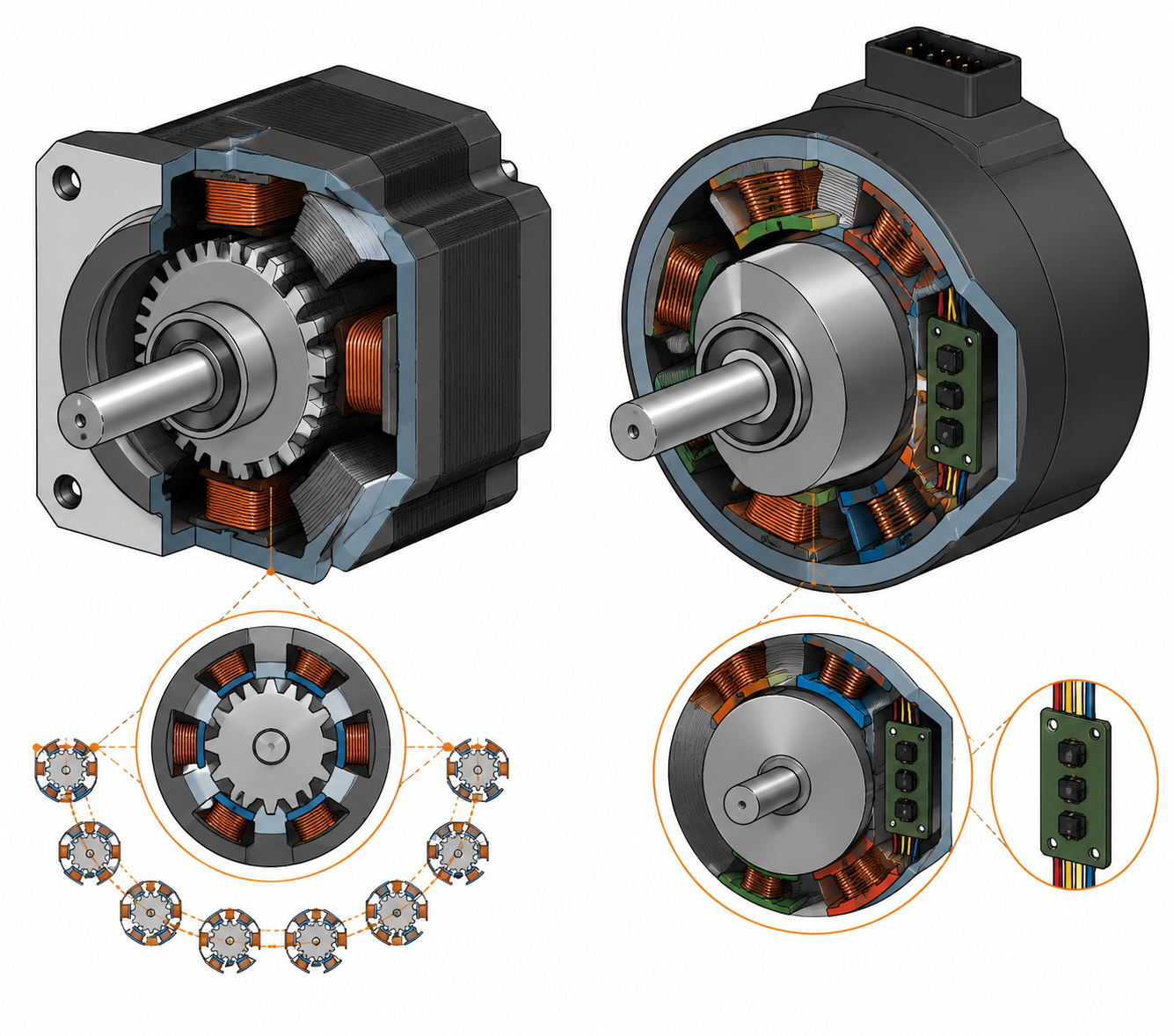
Despite surface similarities, stepper motors and BLDC motors are built around fundamentally different design philosophies.
A stepper motor has a high pole-count stator and a toothed rotor (in the hybrid design). Each electrical pulse advances the shaft by a fixed step angle — typically 1.8°, giving 200 steps per revolution. This "count-the-pulses" approach enables open-loop position control: no encoder feedback is needed because the controller simply tracks how many steps it has commanded. For a deeper look at how this mechanism works, refer to our stepper motor working principle guide.
A BLDC motor typically has three phases and a lower pole count. It is essentially a DC motor with the mechanical commutator replaced by electronics. A BLDC drive continuously reads Hall sensor signals to determine rotor position and decide which phase to energize next — making it an inherently closed-loop system from the moment it powers on.
In short: stepper motors position by counting pulses; BLDC motors regulate speed and torque through continuous sensor feedback.
Torque and Speed: The Most Critical Dimension
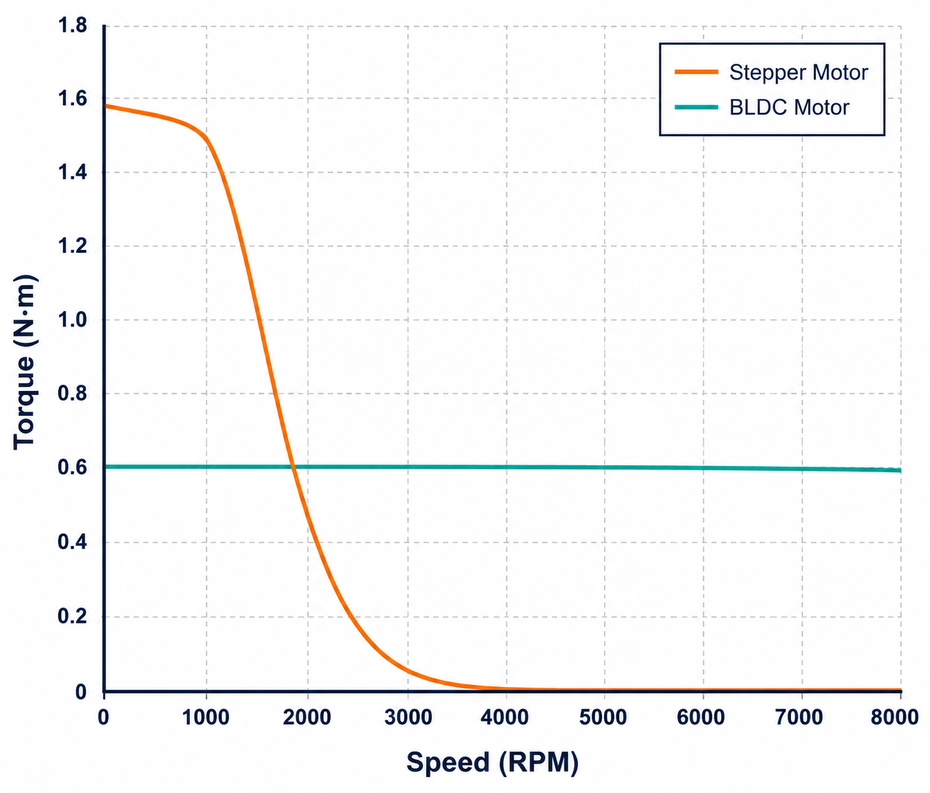
The torque-speed curve is where the two motor types diverge most clearly, and it is the single most important factor in application matching.
Stepper motors excel at low speed. In the 0–600 RPM range, a stepper delivers strong, stable torque including static holding torque when the shaft is at rest. This is a native capability: with full current applied, the motor holds its position against load without any additional brake mechanism. However, as speed increases, winding inductance limits current rise time and output torque drops sharply. Most industrial stepper motors lose the majority of their usable torque above 1,000 RPM. For a detailed breakdown of how output torque varies with pulse frequency, see our stepper motor torque curve explained.
BLDC motors are designed for sustained mid-to-high speed operation. In the 3,000–10,000 RPM range, a well-matched BLDC system delivers smooth, consistent torque at efficiencies of 85–92%. At very low speeds (below 50 RPM), however, BLDC motors can exhibit cogging and torque ripple caused by commutation timing, making them less smooth than steppers at crawl speeds.
| Characteristic | Stepper Motor | BLDC Motor |
|---|---|---|
| Low-speed torque (0–600 RPM) | Excellent — strong holding torque | Moderate — some cogging at very low RPM |
| High-speed performance (>1,000 RPM) | Poor — torque drops sharply | Excellent — rated range up to 10,000+ RPM |
| Static holding torque | Native — no extra hardware needed | Requires a separate brake module |
| Continuous operation efficiency | ~65–70% at rated conditions | 85–92% typical |
| Torque ripple / smoothness | Moderate (microstep control helps) | Low — very smooth in rated speed range |
Open-Loop vs. Closed-Loop: Real Engineering Implications
This is the most practically significant architectural difference between the two motor types.
Stepper motors typically run open-loop. The controller fires pulses and assumes the motor follows exactly. Under normal loads this works well — a properly sized stepper holds positioning accuracy of ±5% of one full step, and errors do not accumulate over time. The problem arises when instantaneous load torque exceeds the motor's pull-out torque: the rotor "skips" (loses steps) and the controller has no way of knowing. In a 3D printer this might mean a slightly shifted print; in an industrial dispensing system it could mean a dosing error or a machine fault. Upgrading to a closed-loop stepper (with an encoder) solves this, but increases system cost. Our complete stepper motor technical guide covers closed-loop stepper configurations in detail.
BLDC motors are closed-loop by design. Hall sensors provide continuous rotor position feedback, so the drive can compensate for load changes in real time. If the motor is overloaded, the drive raises an alarm and stops the system rather than silently losing position. For applications where an undetected positioning error would cause quality failures, product damage, or safety incidents, this inherent fault detection is a meaningful reliability advantage.
Efficiency and Heat Generation
There is a thermal characteristic of stepper motors that engineers frequently underestimate when sizing systems for 24/7 operation.
By default, a stepper motor driver supplies full rated current to the windings at all times — whether the motor is moving or simply holding its last commanded position. This means a stepper in a "hold" state consumes nearly the same power as one running at moderate speed. In a multi-axis machine with several stepper axes sitting idle between cycles, this constant current draw adds up to measurable operating cost and requires careful thermal management.
BLDC motors draw current proportional to actual mechanical load. At light load or zero speed, power consumption drops substantially. Over a full operating year on a production line, this efficiency difference can justify a BLDC system's higher upfront cost. Stepper motors can activate a "current reduction" mode during hold — typically halving the holding current — but this also halves holding torque, which is unacceptable in applications where the motor must resist external forces while stationary.
Positioning Accuracy: A More Nuanced Picture
The assumption that "closed-loop always means higher accuracy" deserves some scrutiny.
A standard hybrid stepper motor has a native step accuracy of ±5% of one step angle — for a 1.8° motor this works out to ±0.09°, and crucially, this error is non-cumulative. The motor can drift within that window per step, but it will not gradually drift further over thousands of steps. With microstepping, the effective resolution can be pushed to 1/256 of a step (51,200 steps per revolution at 1.8° base), giving positional resolution around 0.007° per command. For the mathematical relationship between step angle, phase count, and resolution, see our step angle explainer.
A BLDC motor's positioning accuracy is directly tied to its encoder resolution. A budget BLDC with a low-resolution Hall sensor array may actually offer worse point-to-point positioning than a well-tuned open-loop stepper. Only a high-resolution encoder-equipped BLDC servo system consistently outperforms a stepper on dynamic positioning accuracy across a full speed range. For pure point-to-point motion — step to A, hold, step to B — stepper motor accuracy is sufficient for the vast majority of industrial automation tasks.
Phase Count and Its Practical Impact
Stepper motor phase configuration also affects which applications are best served. Two-phase hybrid steppers are the industrial standard: mechanically simple, widely supported by drivers, and offering a good balance of torque and smoothness. Five-phase steppers deliver lower vibration and finer step resolution but require substantially more expensive drivers. For most OEM automation applications, a 2-phase hybrid stepper with microstepping covers the vast majority of positioning requirements. A detailed performance comparison across phase configurations is available in our 2-phase vs 3-phase vs 5-phase stepper motor comparison.
BLDC motors are universally 3-phase. The main driver-level distinction is between trapezoidal (block) commutation and sinusoidal commutation — the latter produces smoother torque output and is preferred in motion-sensitive applications such as medical devices and precision instruments, though it requires more processing power in the drive.
Total Cost of Ownership
Motor unit price is only one part of the procurement equation. The full system cost — drive electronics, wiring complexity, commissioning time, and long-term energy consumption — often tells a different story.
| Cost Component | Stepper Motor System | BLDC Motor System |
|---|---|---|
| Motor unit (NEMA 23 equivalent) | Lower ($15–$80 typical) | Higher ($40–$200+) |
| Drive / controller | Moderate ($20–$80) | Higher — Hall sensor interface required ($50–$150+) |
| Wiring complexity | Simple (4-wire bipolar or 6-wire) | Higher — motor power + sensor cable harness |
| Commissioning effort | Low — pulse/direction parameters straightforward | Moderate — PID tuning required |
| Ongoing energy cost | Higher — constant holding current | Lower — load-proportional current draw |
For OEM manufacturers building machines with 4–8 motion axes, a stepper-based system typically saves 30–50% on initial system cost. Over a 5-year product lifecycle at high duty cycles, a BLDC system may recover that difference through energy savings — though this calculation varies significantly by application.
The Case for Hybrid Stepper Motors
HDB Motors' core product line is built around the hybrid stepper motor architecture — and for good engineering reasons. The hybrid design combines a permanent magnet rotor with precision-toothed end caps and a multi-pole stator, giving it substantially higher torque density, better step accuracy, and improved high-speed performance compared to pure permanent magnet stepper designs. In NEMA 23 (57mm) and NEMA 34 (86mm) frame sizes, hybrid steppers consistently outperform PM designs on the metrics that matter most in industrial positioning applications.
If you are evaluating which stepper construction suits your load requirements, the key trade-offs between motor architectures are covered in our hybrid vs PM stepper motor comparison and our broader overview of stepper motor types: PM, VR, and hybrid.
Closed-Loop Stepper: The Middle Ground
It is worth explicitly addressing a third option that often gets lost in the binary stepper vs. BLDC framing: the closed-loop stepper motor.
A closed-loop stepper pairs a standard hybrid stepper motor with a rotary encoder. The drive monitors actual shaft position against commanded position and applies correction if a discrepancy develops. This eliminates the lost-step failure mode while preserving the stepper's native low-speed torque advantage and relatively simple control interface. High-speed torque performance also improves because the drive can optimize current phase in real time rather than running fixed open-loop current profiles.
For applications sitting in the grey zone between the two motor types — variable loads, moderate speeds, cost-conscious procurement — a closed-loop stepper frequently delivers the best value combination. It is not the right answer for every application, but it is one that is often overlooked when engineers frame the decision as a strict stepper-vs-BLDC binary.
Application-Based Selection Guide
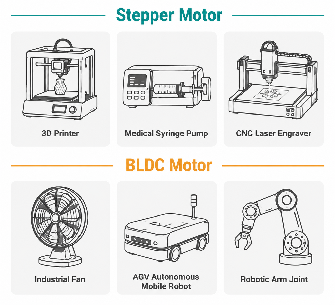
Stepper motors are typically the right choice for:
3D printers and laser engravers — low-speed precision positioning, cost-sensitive volume production
Automated packaging and dispensing — intermittent indexing motion with defined hold positions
Laboratory and medical instruments — syringe pumps, microscope focus stages, low-speed precision displacement
Valve and gate actuators — need to hold position with power applied against back-pressure
Light-to-medium CNC machines — NEMA 23 hybrid steppers with microstepping drivers handle most router and engraver axis requirements
BLDC motors are typically the right choice for:
Industrial fans and high-speed pumps — continuous high-speed operation where efficiency directly reduces operating cost
AGV drive wheels — dynamic load variation requires closed-loop protection against stall
Robot joints and collaborative arms — high-speed range with dynamic torque demands
Power tools and electric vehicles — high power density and efficiency are primary requirements
Medical and precision instruments requiring ultra-smooth rotation — sinusoidal commutation BLDC outperforms stepper at these noise/vibration levels
Decision Framework
If you prefer a systematic approach, work through these six questions in order:
Peak operating speed: Does your application require sustained operation above 1,000 RPM? If yes, lean toward BLDC.
Load predictability: Is the mechanical load well-defined and consistent? If yes, open-loop stepper is viable. If load varies unpredictably, consider closed-loop stepper or BLDC.
Hold position requirement: Must the motor maintain position under external load when stopped? If yes, stepper's native holding torque is an advantage; BLDC requires additional brake hardware.
Duty cycle: Is the machine running 24 hours at high speed? Long-term BLDC efficiency advantages become relevant. Intermittent or low-duty applications reduce this factor.
System budget: Is initial cost the primary constraint? Stepper systems offer lower entry cost per axis. Is lifecycle cost more important? Factor in BLDC energy savings over the product's operational lifespan.
Fault tolerance: Would an undetected positioning error cause quality failures or safety hazards? If yes, open-loop stepper is the wrong choice — evaluate closed-loop stepper or BLDC.
Working through these six questions in sequence will place most real-world applications clearly into one category. Cases that remain ambiguous after the last question are usually good candidates for closed-loop stepper motors, which bridge the gap between the two architectures.
Frequently Asked Questions
Can a stepper motor replace a BLDC motor in a high-speed spindle application?
Generally not. A high-speed spindle running at 3,000+ RPM continuously is precisely the application where stepper motor torque has already collapsed to nearly zero. BLDC or AC induction motors are the appropriate technology for spindle drives above 1,500 RPM.
Is a BLDC motor always more accurate than a stepper?
Not necessarily. A BLDC motor with basic Hall sensor feedback may have lower point-to-point positioning resolution than a properly microstepped hybrid stepper. Only a BLDC configured as a servo (with a high-resolution encoder and closed-loop position control) consistently delivers higher dynamic accuracy.
Why does my stepper motor get hot even when not moving?
Stepper motor drivers maintain holding current through the windings whenever the motor is energized, regardless of whether it is moving. This constant current is the primary source of heat in idle stepper systems. Enabling the driver's current-reduction feature during hold reduces heat generation, but at the cost of reduced holding torque.
What is the main advantage of a hybrid stepper motor over a PM stepper?
Hybrid steppers combine a permanent magnet with toothed iron pole structures, giving them significantly higher torque density, finer step resolution (1.8° or 0.9° vs. typically 7.5° for PM motors), and better high-speed performance. They dominate industrial NEMA frame applications for exactly these reasons. See our hybrid vs PM stepper comparison for a full breakdown.
Is a closed-loop stepper motor the same as a servo motor?
Functionally similar in that both use encoder feedback for position correction, but mechanically different. A closed-loop stepper retains the stepper's multi-pole rotor and strong low-speed holding torque; a traditional servo uses a BLDC or brushed DC motor with a smoother torque curve optimized for continuous dynamic motion. Closed-loop steppers are typically lower cost but have a narrower high-speed range than servo systems.
Ready to Select the Right Motor for Your Application?
HDB Motors manufactures hybrid stepper motors in NEMA 17, NEMA 23, and NEMA 34 frame sizes, with standard and custom winding options for a wide range of automation applications. If you have completed the selection framework above and have identified stepper motors as the right fit, our engineering team can help you confirm the correct torque, current rating, and driver pairing for your specific load profile.
| Standard lead time | 7–15 days for stocked NEMA 23 and NEMA 34 hybrid stepper motors |
| Custom winding | Available for OEM volume orders with specific voltage or inductance requirements |
| Sample policy | Engineering samples available for qualified OEM evaluation projects |
View Product Range ⇩ Download Product Catalog (PDF) Contact Engineering Team