
Stepper motors deliver precise, incremental rotary motion in industrial automation systems, converting digital pulses into exact shaft positions without feedback sensors.Design engineers and OEM factories rely on them for open-loop control in CNC machines, robotics, and packaging equipment where position accuracy down to 0.9° steps is critical.
Unlike continuous DC motors, steppers hold position against load torque even when unpowered in some designs, making them ideal for high-holding-torque applications in motion control. HDBMotor offers NEMA-standard hybrid steppers optimized for USA, Germany, Europe, and South Korea markets, balancing cost, torque, and reliability for industrial integrators.
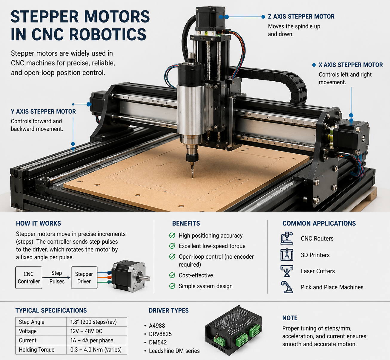
This pillar page covers stepper motor fundamentals, types, performance curves, selection criteria, and OEM sourcing strategies to help procurement managers build robust automation systems.
How Stepper Motors Work
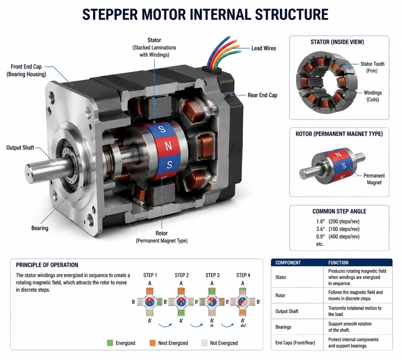
Stepper motors operate by energizing stator coils in sequence to generate rotating magnetic fields that align the rotor in discrete steps. Each electrical pulse advances the shaft by a fixed angle, typically 1.8° for 200 steps per revolution, enabling digital position control without encoders.
The stator features multiple pole pairs with windings, while the rotor—permanent magnet, reluctance, or hybrid—locks into alignment via electromagnetic attraction. Drivers interpret step/direction signals to sequence current through phases, producing smooth or microstepped motion based on control mode.
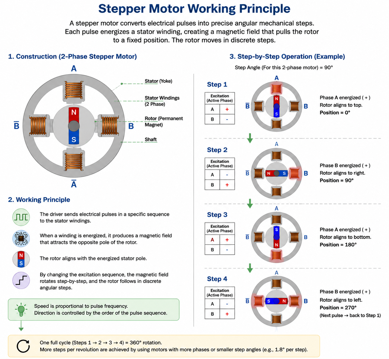
Stepper Motor Working Principle
At core, the principle relies on electromagnetic alignment: current in stator coils creates a magnetic field; the rotor aligns its poles or teeth to minimize reluctance. Sequential phase energization—full-step, half-step, or microstep—rotates the field, pulling the rotor stepwise.
In bipolar hybrids, H-bridge drivers reverse current polarity per coil for bidirectional fields, maximizing torque from all windings. Pulse frequency determines speed, while current limits torque; resonance occurs at 50-150 Hz without damping.
For featured snippet: Stepper motors work by converting electrical pulses into precise mechanical steps via sequential stator coil energization, rotating the magnetic field to align the rotor.
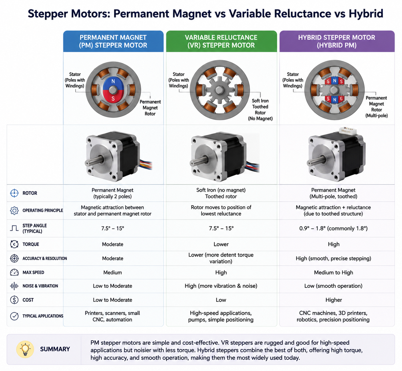
Permanent Magnet
Permanent magnet (PM) steppers use axial magnets in the rotor for detent torque, suiting low-speed, high-holding applications like printer heads. They offer good torque but lower resolution (often 7.5° steps) and speed than hybrids.
Variable Reluctance
Variable reluctance (VR) rotors are soft iron with teeth, aligning to minimize magnetic reluctance paths without magnets. High speed and resolution but no detent torque; used in precision instruments.
Hybrid Stepper Motors
Hybrid designs combine PM rotor with toothed caps and stator for superior torque, resolution (0.9°-1.8°), and speed—dominant in industrial NEMA sizes. HDBMotor hybrids excel in CNC and robotics with minimal step loss under load.
Step Angle and Resolution
Step angle θ = 360° / (steps per revolution), e.g., 1.8° for 200-step motors. Resolution improves via microstepping: 1/16th yields 3200 steps/rev or 0.1125°.
Formula: Steps/rev = phases × rotor teeth / m (microsteps). Engineers calculate load matching: resolution (deg/step) = 360 / steps/rev. For high-precision OEM apps, pair with 0.9° hybrids.
Torque Curves Explained
Torque-speed curves plot available torque vs. pulse frequency: pull-in (start/stop) max at low speed, decreasing hyperbolically; pull-out (sustained) higher but requires ramping. Resonance dip at 100-200 steps/sec demands microstepping or dampers.
Curve regions: constant torque to ~200 RPM, then inductive drop-off. Select drivers boosting voltage for flatter curves in high-speed apps.
Holding Torque vs Running Torque
Holding torque (static) is max at zero speed with full current, resisting loads without motion. Running torque (pull-out) declines with speed due to inductance/back-EMF; pull-in is lower for direct starts.
In industrial use, holding suits clamps; running drives axes—ensure load<80% pull-out at max speed. Hybrids offer 2-15 Nm holding in NEMA 23-42.
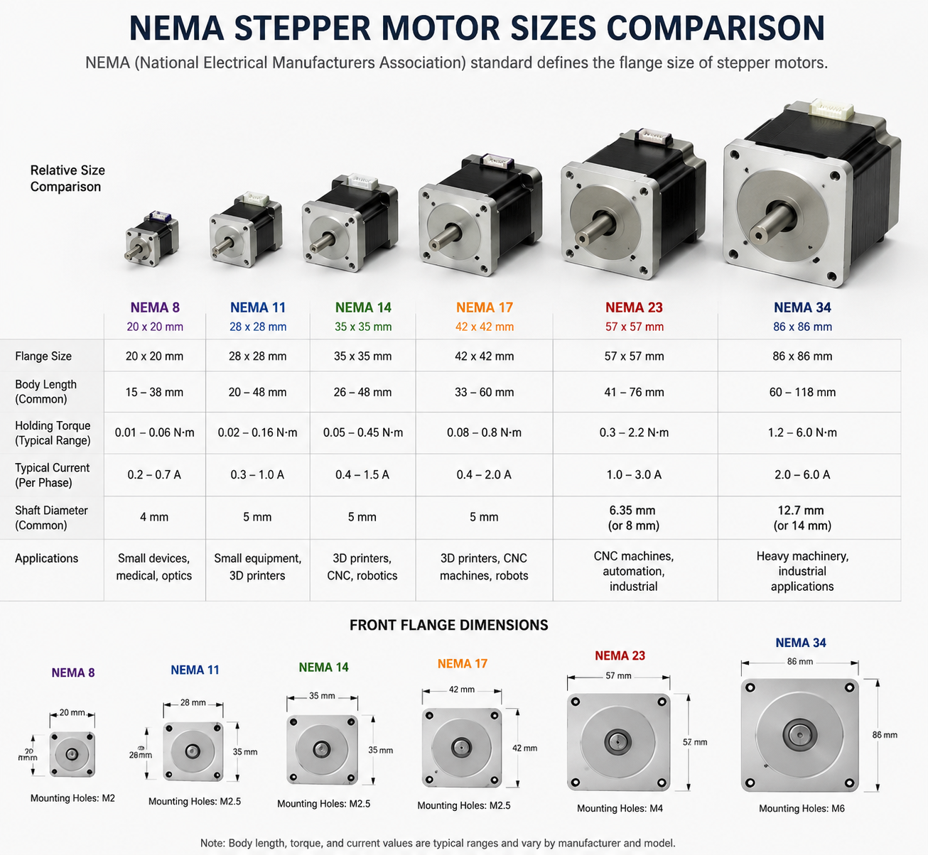
NEMA Stepper Motor Sizes
NEMA standards define faceplate dimensions: NEMA 17 (42mm) for light CNC, NEMA 23 (57mm) for medium routers. Larger NEMA 34/42 handle heavy industrial loads.
| NEMA Size | Frame (mm) | Typical Holding Torque (Nm) | Applications |
|---|---|---|---|
| NEMA 17 | 42x42 | 0.2-0.88 | 3D printers, small robots |
| NEMA 23 | 57x57 | 0.59-3.4 | CNC spindles, AGVs |
| NEMA 34 | 86x86 | 2.8-15 | Heavy automation |
Learn NEMA 17 vs NEMA 23 differences for your build.
Closed Loop Stepper Motors
Closed-loop adds encoders for feedback, correcting lost steps and boosting high-speed torque vs. open-loop. Ideal for dynamic loads in robotics; HDBMotor closed-loop systems maintain 100% accuracy.
Advantages: higher speed/torque, efficiency; drawbacks: cost, complexity. See our closed loop stepper motors page.
Stepper Motor Drivers
Drivers handle current chopping, microstepping (1/256), and interfaces (step/dir, PWM). Bipolar H-bridges for hybrids; select by motor current (1-10A).
Chopper types regulate torque; advanced ICs like MP6501A prevent overheating. Explore stepper motor drivers.
Stepper Motor Wiring Basics
Bipolar: 4 wires (two coils A+/A-, B+/B-); unipolar: 5-6 with center taps. Sequence: 1-2-3-4 for full-step CW.
Miswiring causes vibration; use A4964 diagrams for verification. Details in stepper motor wiring guide.
Microstepping Technology
Microstepping sinusoidally varies phase currents for 1/32+ resolution, reducing resonance/vibration. Tradeoff: lower torque per step, potential skipping at extremes.
Essential for smooth CNC; drivers like TMC2209 enable 256 microsteps.
Stepper Motor Applications
CNC
XY/Z axes positioning; NEMA 23 hybrids for rigidity.
Robotics
Joint actuation; precise steps for end-effectors.
Medical Equipment
Pump dosing, scanner beds; hygiene-rated hybrids.
Packaging Machinery
Fill/seal indexing; high cycle rates.
AGV
Wheel drive/navigation; closed-loop for loads.
Stepper Motor vs Servo Motor
| Aspect | Stepper | Servo |
|---|---|---|
| Control | Open-loop pulses | Closed-loop feedback |
| Torque/Speed | High low-speed hold | High dynamic speed |
| Cost | Lower | Higher |
| Precision | Step-based | Continuous ±0.01° |
Steppers for cost-sensitive positioning; servos for velocity. Full vs servo comparison.
Stepper Motor Selection Guide
1. Calculate load torque + inertia + accel.
2. Match NEMA size/holding >1.5x load.
3. Verify speed-torque curve.
4. Driver current/voltage.
5. Microsteps for res. HDBMotor consult for custom. See torque calculator.
Common Stepper Motor Problems
Lost steps: overload > pull-out.
Overheating: high current, poor cooling.
Resonance: 100Hz vibration; microstep/damp.
Troubleshoot: check wiring, ramp rates. Guide: overheating fixes.
OEM & Industrial Sourcing Guide
Evaluate factories on ISO certs, MOQ, lead times, customization (shafts/gears). HDBMotor: 20+ years, global shipping, engineering support for USA/EU/Korea.
FAQs
How do stepper motors work?
By sequential coil energization creating rotating fields for step alignment.
What is a closed loop stepper motor?
Open-loop with encoder feedback for error correction.
Stepper vs servo motor?
Steppers: simple, low-speed torque; servos: high-speed precision.
What is holding torque?
Max static torque at rest.
NEMA 17 vs 23?
17: light duty; 23: higher torque.
How to calculate stepper torque?
Load + friction + accel; tools here.
Why do steppers overheat?
Constant current draw; use choppers, heatsinks.
What is microstepping?
Fractional steps via current modulation.
Best stepper for CNC?
NEMA 23 hybrid, 2-4A driver.
Stepper motor wiring colors?
Bipolar: A+ green, A- red, B+ blue, B- black typical.
Conclusion
Stepper motors anchor industrial motion control with unmatched position certainty and torque. Partner with HDBMotor for tailored solutions driving your automation forward. Request engineering consultation today.