
When an automation engineer begins specifying motion control components, one question sits at the foundation of every purchasing decision: how exactly does a stepper motor work, and what does that mean for my application?
The stepper motor working principle is deceptively simple — convert digital pulses into precise mechanical rotation — but the engineering reality beneath that statement determines whether your positioning system hits its accuracy targets or misses them entirely. Understanding phase excitation, step angle, and torque behavior isn't academic theory. It's the difference between a machine that runs reliably for years and one that stalls under load on day three.
This guide walks you through the complete working principle, from magnetic fundamentals to practical selection parameters. We connect every theoretical concept directly to a real-world purchasing decision, so by the end you'll know exactly what specifications matter for your application.
If you're looking for a broader overview of stepper motor types and construction before diving into operating principles, our complete stepper motor technical guide covers frame sizes, winding configurations, and environmental ratings in detail.
How a Stepper Motor Converts Electrical Pulses into Mechanical Movement
At its core, a stepper motor is a brushless DC motor that divides a full rotation into a fixed number of equal steps. Unlike a conventional DC motor that spins continuously when voltage is applied, a stepper motor moves in discrete angular increments — each one triggered by a digital pulse from the driver.
Here's what happens inside the motor during each pulse:
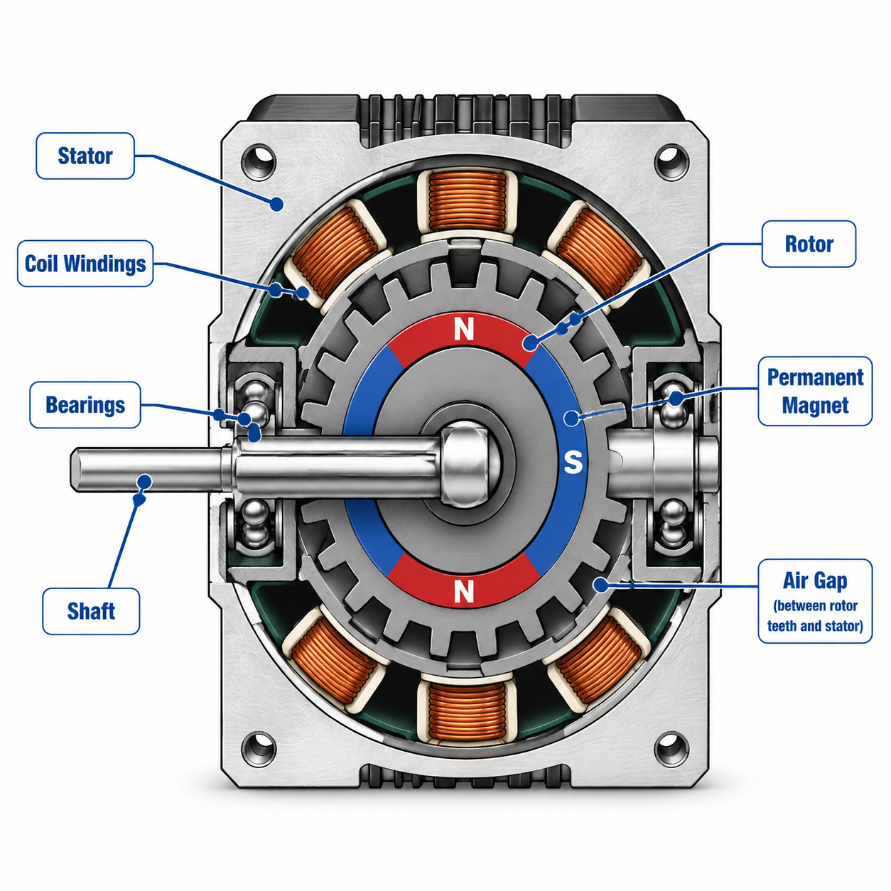
The driver energizes one or more stator windings in a specific polarity pattern.
This creates a magnetic field in the stator.
The rotor, which contains permanent magnets or a magnetically soft toothed core, aligns itself to the stator field.
The rotor locks into the position of minimum magnetic reluctance.
When the driver switches to the next winding combination, the rotor moves to the new alignment position.
This is the fundamental stepper motor working principle: controlled magnetic attraction and repulsion creating predictable, repeatable motion. Each switch of the winding energization pattern produces one "step" — a fixed angular rotation.
The critical engineering insight: because the rotor moves to a defined magnetic equilibrium position, not to an arbitrary point determined by load and speed, stepper motors achieve open-loop position control without encoders. Send 200 pulses, and you know the shaft has rotated exactly 360 degrees (for a standard 1.8° step angle motor). This deterministic behavior is why steppers dominate positioning applications from laboratory automation to CNC routers.
For a deeper walkthrough of the electromagnetic sequence — including animated explanations of stator-rotor interaction — see our article on how stepper motors work, which breaks down the excitation cycle step by step.
Step Angle Explained: The Foundation of Positioning Accuracy
What Determines Step Angle
The step angle is the smallest angular movement a stepper motor can make under full-step operation. It's defined by the mechanical construction of the motor — specifically, the number of rotor teeth and stator poles.
The formula:
Step Angle = 360° ÷ (Number of Rotor Teeth × Number of Phases)
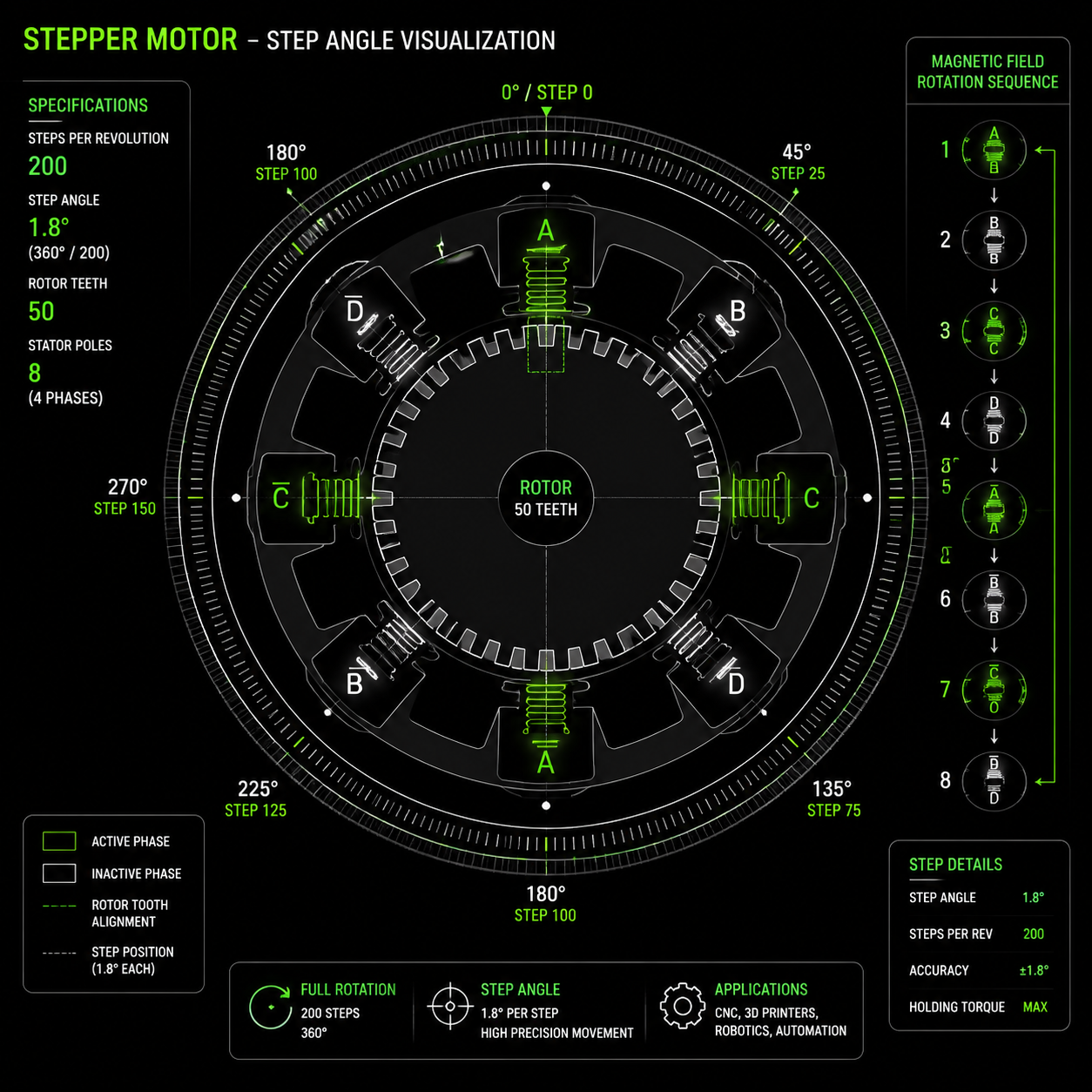
For a typical hybrid stepper motor with 50 rotor teeth and 2 phases:
Step Angle = 360° ÷ (50 × 2) = 3.6° per full step
But this 3.6° is per half-cycle. In standard full-step operation where both phases are used sequentially, a 50-tooth rotor combined with the 2-phase stator arrangement yields the industry-standard 1.8° step angle (200 steps per revolution).
Other common step angles and their corresponding steps per revolution:
The step angle of a stepper motor determines its positioning resolution and is a key parameter in selecting motors for precision motion control systems.
| Step Angle | Steps Per Revolution | Typical Application |
|---|---|---|
| 0.9° | 400 | High-precision positioning, semiconductor equipment |
| 1.8° | 200 | General automation, CNC machines, 3D printers |
| 3.6° | 100 | Low-cost industrial applications, valve actuators |
| 7.5° | 48 | Legacy systems, rotary indexers |
| 15° | 24 | Low-cost consumer devices |
Why Step Angle Matters for Purchasing Decisions
When you select a stepper motor, the step angle directly determines your system's theoretical positioning resolution before microstepping. A 1.8° motor driving a 5mm pitch ball screw delivers 0.025mm linear resolution per full step. The same setup with a 0.9° motor delivers 0.0125mm — double the resolution without changing anything else in the drivetrain.
However, smaller step angles typically come at a cost premium and may reduce maximum holding torque slightly due to the finer tooth geometry. The purchasing decision balances resolution requirements against torque and budget constraints.
Phase Configurations: 2-Phase, 3-Phase, and 5-Phase Motors
Understanding Phases in Stepper Motors
A "phase" in stepper motor terminology refers to an independent winding group on the stator. When you energize a phase, it creates a magnetic pole pair. The number of phases determines the excitation pattern complexity and affects smoothness, torque ripple, and resonance behavior.
2-Phase Stepper Motors:
The industry workhorse. Two independent windings (often split into A+ / A- and B+ / B-) create a rotating magnetic field through sequential energization. These motors account for roughly 80% of all stepper motor applications. They offer an excellent balance of cost, driver simplicity, and performance.
Common excitation modes for 2-phase motors:
Stepper motor excitation modes define how stator windings are energized in sequence. This directly affects step resolution, torque output, and motion smoothness.
| Excitation Mode | Sequence Pattern | Step Size | Torque | Smoothness |
|---|---|---|---|---|
| Full-Step (1 phase on) | A → B → A' → B' | Full step angle | Lowest | Rough (high torque ripple) |
| Full-Step (2 phases on) | AB → BA' → A'B' → B'A | Full step angle | ~1.4× single-phase torque | Moderate |
| Half-Step | A → AB → B → BA' → A' → A'B' → B' → B'A | Half step angle | Variable per step | Improved |
| Microstepping | Sinusoidal current control | Fractional step | Smooth torque output | Excellent |
3-Phase Stepper Motors:
Three windings spaced 120° apart. The three-phase design inherently produces smoother motion because the torque ripple frequency is higher and amplitude lower. These motors excel in applications sensitive to vibration, such as medical imaging equipment or precision metrology. Driver electronics are more complex and generally more expensive than 2-phase equivalents.
5-Phase Stepper Motors:
Five windings produce 500 or 1000 full steps per revolution (0.72° or 0.36° step angles). The primary advantages are extremely smooth motion and reduced resonance, making 5-phase motors the choice for semiconductor wafer handling, high-end optical systems, and applications where vibration cannot be tolerated. The trade-off: significantly higher cost per unit and fewer driver options on the market.
Selecting the Right Phase Configuration
Your phase selection should follow application requirements, not theoretical ideals:
Choose 2-phase for general automation, cost-sensitive projects, and applications where microstepping can address smoothness concerns.
Choose 3-phase when vibration reduction matters but 5-phase cost is prohibitive.
Choose 5-phase only when both ultra-smooth motion and native high resolution are mandatory — and budget allows.
Torque Characteristics: Holding Torque, Pull-In Torque, and Pull-Out Torque
Understanding stepper motor torque curves is essential because torque is not constant. It drops significantly as speed increases, and different torque definitions apply at different operating conditions.
Holding Torque
Holding torque is the maximum static torque the motor can withstand with rated current applied to the windings but no rotation. This is the specification you'll see on most datasheets prominently — but it only applies at zero speed.
A typical NEMA 23 stepper might be rated at 1.26 N·m holding torque. This number tells you the motor can resist a 1.26 N·m external torque trying to rotate the shaft while energized at standstill. It does not tell you what torque is available at 500 RPM or 1000 RPM.
Pull-In Torque
Pull-in torque is the maximum load torque against which the motor can start and stop without losing synchronism — without ramping acceleration. Think of it as the "instant-on" torque capacity. Pull-in torque is always lower than holding torque and decreases as step rate increases.
Pull-Out Torque
Pull-out torque is the maximum torque the motor can develop while running at constant speed — the torque at which the motor will stall if further loaded. This is the most important number for applications where the motor runs continuously at speed. Like pull-in torque, pull-out torque decreases as speed increases, but pull-out torque values are typically higher than pull-in torque at the same speed because the rotor's momentum helps carry it through.
Torque-Speed Relationship Table (Typical NEMA 23, 1.8° Stepper Motor)
The torque-speed characteristic is one of the most important performance curves of a stepper motor. As speed increases, available torque decreases due to inductance and back EMF effects.
| Speed (RPM) | Pull-Out Torque (N·m) | % of Holding Torque | Operating Region |
|---|---|---|---|
| 0 | 1.26 (Holding) | 100% | Static holding |
| 100 | 1.05 | 83% | Low-speed positioning |
| 300 | 0.72 | 57% | Moderate speed operation |
| 600 | 0.42 | 33% | Continuous motion region |
| 1000 | 0.25 | 20% | High-speed operation (near limit) |
| 1500 | 0.12 | 10% | Light-load operation only |
This torque decay is caused by winding inductance. As step rate increases, the current has less time to rise in each winding before the next commutation. The driver must overcome this inductance — and higher drive voltages help maintain current at higher speeds. This is why a 48V driver can extract significantly more high-speed torque from the same motor compared to a 24V driver.
Key purchasing takeaway: Always check the torque-speed curve for your expected operating speed. A motor with impressive holding torque may be completely inadequate at your application's running speed.
Full-Step, Half-Step, and Microstepping: Resolution vs. Torque Tradeoffs
Stepper motor drivers provide multiple excitation modes, each representing a tradeoff between positional resolution, torque smoothness, and system complexity.
Full-Step Operation
In full-step mode, the driver alternates between winding energization states at the motor's natural step interval. For a 1.8° motor, that's 200 steps per revolution. Full-step operation is simple, requires the least driver sophistication, and delivers maximum torque per step at low speeds.
The downside: significant torque ripple. At certain speeds, full-step excitation can excite mechanical resonance in the motor-load system, causing vibration, audible noise, and in severe cases, loss of synchronism (stalling). This resonant behavior typically occurs between 100–200 RPM for many NEMA 23 motors.
Half-Step Operation
Half-step mode alternates between single-phase and dual-phase energization, producing 400 steps per revolution from a 1.8° motor. The alternating torque between strong (two phases on) and weak (one phase on) steps creates uneven motion but doubles resolution at minimal additional driver complexity.
Modern drivers rarely implement pure half-stepping. Instead, they use microstepping to achieve smoother fractional steps.
Microstepping
Microstepping modulates current in the windings using sinusoidal waveforms, creating intermediate positions between full-step points. Common microstep resolutions: 2x, 4x, 8x, 16x, 32x, 64x, 128x, and 256x.
A 1.8° motor driven at 16x microstepping produces 3200 microsteps per revolution — a theoretical resolution of 0.1125° per microstep.
Critical engineering caveat: Microstepping improves smoothness dramatically, but it does not necessarily improve accuracy proportionally. The incremental torque available to hold intermediate microstep positions decreases as the fraction decreases. Very fine microsteps (beyond 16x or 32x) produce diminishing returns in actual positioning accuracy. They're primarily useful for reducing vibration and audible noise, not for achieving sub-micron true position resolution.
Comparison: Excitation Mode Selection Guide
Stepper motor drive mode directly affects resolution, torque ripple, and motion smoothness. Higher microstepping levels improve motion quality but do not increase actual torque output.
| Drive Mode | Steps/Rev (1.8° Motor) | Relative Torque Ripple | Best Application |
|---|---|---|---|
| Full-Step | 200 | High — resonance risk | Low-speed, cost-sensitive indexing systems |
| Half-Step | 400 | Moderate | Legacy automation systems |
| 4x Microstep | 800 | Low | General industrial automation |
| 8x Microstep | 1600 | Very low | Smooth motion systems |
| 16x Microstep | 3200 | Minimal | 3D printing, light CNC systems |
| 32–256x Microstep | 6400–51200 | Near-continuous | Noise-sensitive precision environments |
Driver Selection: Why the Driver Determines Real-World Performance
A stepper motor cannot function without a driver — and the driver's specifications directly control how well the motor performs against its theoretical capabilities.
Key Driver Specifications That Affect Motor Performance
Supply Voltage:
Driver supply voltage is the single most important factor for high-speed torque. Higher voltage forces current into the inductive windings faster, maintaining torque at higher step rates. A motor that delivers 0.5 N·m at 600 RPM with a 24V supply might deliver 0.7 N·m at the same speed with a 48V supply. Always select a driver with the highest voltage rating your budget and safety requirements allow — within the motor's insulation limits.
Current Rating:
The driver must comfortably exceed the motor's rated current. Continuous operation near the driver's maximum current rating causes thermal stress and reduced reliability. A common rule: select a driver rated at least 30% above the motor's rated current.
Microstepping Capability:
Even if you don't need ultra-fine resolution, microstepping provides smoother motion and reduced resonance. Most modern drivers offer at least 16x microstepping as standard.
Control Interface:
Pulse/direction inputs remain the industry standard for simple point-to-point positioning. For more complex motion profiles, drivers with CANopen, Modbus, or EtherCAT interfaces enable networked control, real-time parameter adjustment, and diagnostic feedback.
Common Driver Configuration Mistakes
Setting drive current too low: Reduces torque across the entire speed range. Always set current to the motor's rated value.
Running at insufficient voltage: Chokes high-speed torque. If your application requires torque above 300 RPM, use the highest practical supply voltage.
Ignoring idle current reduction: Many drivers automatically reduce current at standstill to prevent overheating. Verify this setting aligns with your holding torque requirements.
Incorrect microstep setting: Too high produces no real positional benefit; too low produces rough motion.
Common Open-Loop Problems and How to Avoid Them Through Proper Selection
Stepper motors typically operate open-loop — no position feedback. This simplicity is a key advantage, but it creates failure modes that proper motor and driver selection can mitigate.
Missed Steps (Lost Synchronism)
When load torque exceeds the motor's available torque at a given speed, the rotor cannot follow the stator field. Steps are "missed" — the motor continues to receive pulses but falls behind, introducing cumulative position error with no automatic correction.
Prevention through selection:
Size the motor with a minimum 30–50% torque margin above calculated load requirements.
Account for torque drop-off at operating speed, not just holding torque.
Consider acceleration profiles. High inertial loads require ramped acceleration to stay within pull-in torque limits.
Resonance and Mid-Band Instability
Stepper motors exhibit natural resonant frequencies where torque drops sharply and vibration increases. This typically occurs in the 100–200 RPM range for NEMA 23 motors but varies by motor design and load inertia.
Prevention through selection:
Use drivers with anti-resonance or damping features.
Select microstepping drives that smooth current transitions.
Avoid operating continuously in known resonance speed bands. Change gear ratios or operating speeds if your application falls into a resonance zone.
3-phase and 5-phase motors inherently reduce resonance amplitude.
Overheating
Stepper motors draw full rated current at standstill to maintain holding torque. Unlike servo motors that reduce current when not moving, steppers consume power continuously. Motors rated for 80°C rise may exceed 100°C surface temperature in normal operation.
Prevention through selection:
Verify the motor's insulation class matches your operating environment (Class B: 130°C max; Class F: 155°C max).
Use drivers with idle current reduction if the application involves long stationary periods.
Allow adequate mounting surface area for heat dissipation. NEMA 23 motors often require aluminum mounting brackets as heat sinks.
How to Match a Stepper Motor to Your Application: A Selection Checklist
Connecting the working principle to a purchasing decision requires a systematic approach. Use this checklist to translate your motion requirements into motor and driver specifications:
Stepper motor selection is a systematic engineering process that balances torque, speed, resolution, and environmental conditions. Incorrect sizing is one of the most common causes of motion system failure.
| Selection Step | Key Questions | Relevant Motor Specification |
|---|---|---|
| 1. Define Motion Profile | Travel distance, speed, acceleration | Step angle, torque-speed curve |
| 2. Calculate Load Torque | Inertia, friction, external forces | Holding torque, pull-out torque |
| 3. Determine Resolution | Required positioning accuracy | Step angle, microstepping level |
| 4. Check Speed Requirements | Continuous operating RPM | Torque-speed curve performance |
| 5. Evaluate Duty Cycle | Run time vs idle time | Thermal rating, current limit |
| 6. Consider Environment | Temperature, dust, humidity | IP rating, insulation class |
| 7. Select Driver System | Voltage, current, control interface | Driver compatibility |
| 8. Add Safety Margin | 30–50% torque headroom | Motor oversizing or gearing strategy |
This checklist ensures you're not buying based on holding torque alone — the most common and costly mistake in stepper motor procurement.
Frequently Asked Questions
What is the basic working principle of a stepper motor?
A stepper motor operates by energizing stator windings in a precise sequence, creating a rotating magnetic field. The permanent-magnet or toothed rotor aligns to each new field orientation in discrete angular movements called steps. Each digital pulse from the driver advances the rotor by one step angle, enabling open-loop position control.
How is the step angle of a stepper motor calculated?
Step angle equals 360 degrees divided by the product of the number of rotor teeth and the number of phases. For standard hybrid stepper motors with 50 rotor teeth and 2 phases, the natural full-step angle is 1.8°, giving 200 steps per revolution. Microstepping divides these natural steps into smaller increments.
What's the difference between holding torque and running torque?
Holding torque is the maximum static torque the motor can resist at standstill with rated current applied. Running torque (pull-out torque) is the maximum torque available at a given speed before stalling. Running torque decreases as speed increases due to winding inductance limiting current rise time.
Can microstepping improve positioning accuracy?
Microstepping dramatically improves motion smoothness and reduces vibration, but it provides diminishing accuracy returns beyond 16x–32x microstepping. The incremental torque between microsteps becomes very small at high resolutions, meaning actual position accuracy is limited by motor linearity and load friction, not step division alone.
Why does my stepper motor lose steps under load?
Step loss occurs when the load torque exceeds the motor's available torque at the operating speed. This can happen during acceleration if inertial loads aren't accounted for, or at speed if the torque-speed curve wasn't properly evaluated. Solutions include increasing drive voltage, reducing acceleration rates, or selecting a larger motor.
What is the advantage of a 5-phase stepper motor over a 2-phase?
Five-phase stepper motors produce smoother motion with lower torque ripple and higher natural resolution (0.72° or 0.36° per full step) without relying on the driver for microstepping. They also exhibit reduced resonance amplitude. The trade-off is higher cost, limited driver availability, and more complex wiring.
How do I select the right driver for my stepper motor?
Match the driver's current rating to your motor's rated current (preferably with 30%+ headroom), select the highest practical supply voltage within motor limits for better high-speed torque, and ensure the control interface (pulse/direction, CANopen, etc.) integrates with your system. Modern drivers should include microstepping and anti-resonance features.
Conclusion
The stepper motor working principle combines electromagnetic precision with mechanical simplicity to deliver repeatable, controllable motion. Understanding step angle calculation, phase excitation modes, and torque-speed behavior transforms motor selection from guesswork into an engineering decision.
When you evaluate stepper motors for your next project, focus on the specifications that actually govern real-world performance: torque at your operating speed (not just holding torque), driver voltage headroom for high-speed applications, and phase count balanced against motion smoothness requirements. A correctly specified stepper motor and driver pair will deliver years of reliable open-loop positioning.
For assistance selecting the optimal stepper motor and driver combination for your specific application, our engineering team can review your motion requirements and recommend a matched solution. Contact HDBMotor for application engineering support.