
When sizing a stepper motor for a CNC axis or a medical dispensing pump, the step angle is rarely the first parameter engineers look at — and that's usually where positioning errors start. The assumption that "smaller step angle equals better accuracy" gets repeated often enough that it shapes purchasing decisions, but the relationship between step angle, mechanical resolution, and actual positioning performance is more nuanced than that framing suggests.
This article works through the physical basis of step angle, the real engineering differences between 1.8° and 0.9° motors, and what microstepping actually delivers versus what the driver datasheet implies.
Where Step Angle Comes From
A standard two-phase hybrid stepper motor produces motion by sequentially energizing stator windings, which pulls the rotor's permanent magnet teeth into alignment with successive stator poles. The step angle is a direct function of the rotor tooth count and the number of stator phases:
Step Angle = 360° / (Number of Rotor Teeth × Number of Phases × 2)
For a standard 1.8° motor, the rotor has 50 teeth. With two phases and the standard full-step excitation sequence, that gives 200 steps per revolution. A 0.9° motor uses a 100-tooth rotor, doubling the step count to 400 per revolution. The stator geometry changes accordingly — the pole pitch is tighter, which has downstream effects on winding inductance, back-EMF characteristics, and ultimately on how the motor behaves at speed.
This is worth understanding at the construction level because it explains why you can't simply treat a 0.9° motor as a "better" 1.8° motor. They are different mechanical designs with different electromagnetic characteristics, not just a resolution upgrade.
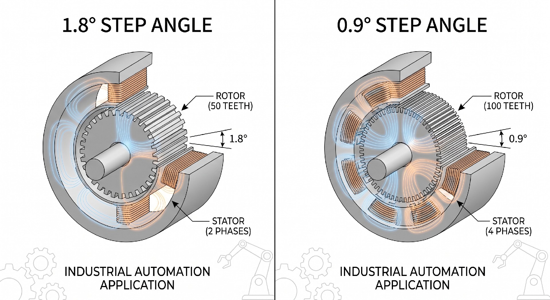
1.8° vs 0.9°: The Engineering Tradeoffs
The 1.8° motor became the industry standard for practical reasons. The 50-tooth rotor geometry produces a relatively strong detent torque and a well-defined magnetic alignment at each full step. This makes the motor tolerant of moderate load disturbances and gives it predictable behavior across a wide speed range. For most CNC axis applications — particularly where the mechanical transmission includes a leadscrew with reasonable pitch — 200 steps per revolution provides adequate open-loop resolution without demanding anything unusual from the driver.
The 0.9° motor's 100-tooth rotor creates a finer magnetic pitch, which reduces the torque ripple per step. In applications where torque ripple translates directly into velocity variation — medical peristaltic pumps, precision dispensing systems, optical positioning stages — this matters. The smoother torque profile at low speeds is the primary reason to specify a 0.9° motor, not the step count itself.
The tradeoff is that the tighter pole pitch increases winding inductance relative to resistance. At higher step rates, the current rise time becomes a limiting factor. A 0.9° motor running at the same RPM as a 1.8° motor is executing twice as many steps per second, which means the driver's current regulation is working twice as hard. Torque rolloff at speed is steeper, and the motor is more sensitive to supply voltage. In practice, 0.9° motors are most useful in low-to-medium speed applications where the smoother torque profile justifies the reduced high-speed performance.
| Parameter | 1.8° Motor (200 steps/rev) | 0.9° Motor (400 steps/rev) |
|---|---|---|
| Rotor teeth | 50 | 100 |
| Steps per revolution | 200 | 400 |
| Torque ripple (full step) | Higher | Lower |
| High-speed torque | Better | Reduced due to inductance |
| Resonance sensitivity | Moderate | Lower fundamental, but harmonics shift |
| Typical application fit | CNC axes, general automation | Medical pumps, optical stages, low-speed precision |
Resonance and Step Angle
Every stepper motor has a natural resonance frequency determined by the rotor inertia and the magnetic spring stiffness at a detent position. For a 1.8° motor under no load, this typically falls somewhere between 100 and 200 Hz — which corresponds to roughly 30–60 RPM in full-step mode. Running through this range without damping produces velocity ripple, audible noise, and in severe cases, missed steps.
The 0.9° motor shifts this resonance point. The higher tooth count changes the magnetic stiffness, and the doubled step rate means the motor passes through its resonance band at a different shaft speed. This can be an advantage or a disadvantage depending on the application's operating speed range. If the system needs to run continuously at a speed that happens to coincide with the 1.8° motor's resonance, switching to a 0.9° motor may solve the problem without requiring microstepping or damping hardware. But if the 0.9° motor's resonance falls in a more critical part of the speed range, the problem shifts rather than disappears.
Load inertia interacts with this directly. A high-inertia load — a heavy gantry, a large rotary table — lowers the resonance frequency and broadens the resonance band. A low-inertia load raises it. This is why resonance behavior observed on a test bench without the actual load attached is often misleading. The motor-load system resonance is what matters, and it needs to be evaluated with the actual reflected inertia in the drivetrain.
Microstepping: What the Driver Does and What the Motor Delivers
Microstepping works by proportioning current between the two phases according to a sine/cosine relationship rather than switching them fully on and off. Instead of snapping between full-step positions, the rotor is held at intermediate positions by the vector sum of the two phase currents. A driver configured for 16× microstepping divides each 1.8° full step into 16 substeps of 0.1125° each, giving 3200 steps per revolution.
The positioning resolution implied by that step count is real in the sense that the driver is issuing 3200 distinct current states per revolution. Whether the rotor actually reaches 3200 distinct mechanical positions is a different question, and the answer depends on the motor's magnetic linearity, manufacturing tolerances, and the load conditions.
The fundamental issue is that the torque-versus-displacement curve of a stepper motor is sinusoidal, not linear. At a full-step position, the motor sits at the peak of its holding torque curve — a stable equilibrium. At a microstep position between two full steps, the holding torque is reduced. At the midpoint between two full steps (the 8th microstep in a 16× scheme), holding torque drops to roughly 70% of the full-step value. Any load torque, friction, or disturbance force that exceeds the available holding torque at that microstep position will cause the rotor to slip to the nearest stable position, which is typically a full-step location.
In practice, microstepping below 1/8 step produces diminishing returns in mechanical positioning accuracy. The primary benefit of high microstepping ratios — 1/16, 1/32, 1/64 — is smoother motion and reduced audible noise, not improved positioning accuracy. For a detailed breakdown of stepper motor electrical and mechanical parameters that affect this behavior, the HDBMotor stepper motor technical guide covers the torque-speed curves and driver interaction in more depth.
| Microstep Setting | Steps/Rev (1.8° motor) | Theoretical Resolution | Practical Positioning Accuracy | Primary Benefit |
|---|---|---|---|---|
| Full step | 200 | 1.8° | ±0.09° (typical) | Maximum torque, simplest driver |
| Half step | 400 | 0.9° | ±0.05° | Reduced resonance, moderate smoothness |
| 1/8 step | 1600 | 0.225° | ±0.05° (load dependent) | Smooth motion, noise reduction |
| 1/16 step | 3200 | 0.1125° | ±0.05° (no improvement) | Smoother velocity profile |
| 1/32 step or finer | 6400+ | <0.06° | No measurable improvement | Noise reduction only |
The ±0.05° figure that appears repeatedly in that table reflects the inherent mechanical accuracy of the motor itself — the tolerance on rotor tooth geometry, stator pole alignment, and bearing runout. This is a manufacturing specification, not a function of step resolution. No amount of microstepping can improve on it. Engineers who need positioning accuracy beyond what the motor's mechanical tolerance allows need closed-loop feedback, not a higher microstep ratio.
System-Level Resolution: Motor to Load
Step angle at the motor shaft is only the starting point. What matters in the application is the resolution at the load — the linear displacement per step for a leadscrew axis, or the angular increment per step for a rotary table.
A 1.8° motor driving a 5mm-pitch leadscrew directly produces 5mm / 200 steps = 0.025mm per full step. With 1/8 microstepping, that becomes 0.003125mm per microstep — which sounds impressive until you account for leadscrew backlash, which in a typical rolled ballscrew is 0.01–0.05mm. The microstep resolution is smaller than the mechanical backlash, making it irrelevant to actual positioning accuracy.
This is a common design error in CNC and automation systems: specifying high microstepping ratios to achieve a resolution number on paper while the mechanical transmission limits real accuracy to a much coarser value. The correct approach is to match the step resolution to the mechanical accuracy of the transmission, then use microstepping only to the extent needed for smooth motion.
Application Selection Logic
For CNC router and mill axis control, the 1.8° motor with 1/8 or 1/16 microstepping covers most requirements. The mechanical transmission — ballscrew pitch, belt reduction ratio — typically limits positioning accuracy to 0.01–0.05mm, which is well within what a standard 200-step motor can resolve. The priority is torque consistency across the operating speed range, which favors the 1.8° design.
In 3D printing, the motion system runs at relatively low speeds with light loads. Torque ripple translates into surface artifacts — the banding visible on printed walls at certain layer heights corresponds to the step frequency interacting with the frame's resonance. Here, 0.9° motors or 1/16 microstepping on 1.8° motors both reduce this effect, and the choice often comes down to driver availability and cost.
Medical peristaltic and syringe pump applications are where 0.9° motors earn their place. Flow rate accuracy depends on velocity uniformity, and the smoother torque profile of the 0.9° motor at low RPM reduces pulsation. These systems also tend to run at fixed, low speeds where the 0.9° motor's reduced high-speed torque is not a constraint.
Packaging indexing systems present a different set of priorities. The motion profile is typically a fast index followed by a dwell — high acceleration, moderate speed, hard stop. Torque at speed matters more than low-speed smoothness. The 1.8° motor's better high-speed torque retention and stronger detent at rest (which helps hold position during the dwell without continuous current) makes it the standard choice here.
| Application | Recommended Step Angle | Microstepping | Primary Constraint |
|---|---|---|---|
| CNC axis (ballscrew) | 1.8° | 1/8 to 1/16 | Torque at speed, transmission accuracy |
| 3D printer (Cartesian/CoreXY) | 0.9° or 1.8° | 1/16 to 1/32 | Surface finish, resonance artifacts |
| Medical pump (peristaltic) | 0.9° | 1/8 | Velocity uniformity, torque ripple |
| Packaging indexer | 1.8° | Full or half step | Acceleration torque, dwell holding |
| Optical positioning stage | 0.9° | 1/8 to 1/16 | Low-speed smoothness, repeatability |
Practical Notes on Driver and Motor Matching
The step angle selection doesn't exist in isolation from the driver. A 0.9° motor running at 1/16 microstepping on a driver with a 24V supply will have a very different torque-speed curve than the same motor on a 48V supply. The higher voltage allows faster current rise in the windings, which partially compensates for the inductance penalty of the 100-tooth rotor at higher step rates. If the application requires a 0.9° motor to run at moderate speeds, the supply voltage needs to be sized accordingly — typically 20–25× the motor's rated voltage is a reasonable starting point for the driver supply.
Current setting also interacts with step angle behavior. Running a motor at reduced current to limit heat dissipation reduces holding torque at each microstep position, which increases the susceptibility to position error under load. In systems where thermal management pushes toward lower current settings, the 1.8° motor's stronger full-step detent provides more margin than the 0.9° motor operating at the same reduced current.
The decision between 1.8° and 0.9°, and the choice of microstepping ratio, should follow from the actual motion requirements: the required resolution at the load, the operating speed range, the load torque and inertia, and the acceptable velocity ripple. Working backward from those constraints to the motor and driver specification produces a more reliable system than working forward from a resolution target on the motor datasheet.
Frequently Asked Questions
Does a smaller step angle always mean better positioning accuracy?
Not in practice. Step angle determines the resolution the motor can theoretically achieve at the shaft. What limits actual positioning accuracy is the mechanical system — leadscrew backlash, belt stretch, bearing play, and the motor's own tooth geometry tolerance. A 0.9° motor in a drivetrain with 0.05mm of backlash does not position more accurately than a 1.8° motor in the same drivetrain. If shaft-level accuracy is the requirement, the motor's mechanical tolerance spec (typically ±0.09° for a 1.8° motor, non-cumulative) is the relevant number, not the step angle.
Can I use high microstepping to replace a closed-loop system?
No. Microstepping controls the current vector, not the rotor position. If the load torque at a microstep position exceeds the available holding torque at that point — which is reduced compared to a full-step position — the rotor will slip without the controller knowing. Open-loop stepper systems have no position feedback by definition. High microstepping ratios reduce velocity ripple and noise, but they do not add position verification. Applications that cannot tolerate missed steps or position drift under variable load need an encoder and closed-loop control, regardless of the microstepping ratio.
Why does my stepper motor vibrate badly at certain speeds but run smoothly at others?
This is resonance. The motor-load system has a natural frequency determined by rotor inertia, load inertia, and magnetic spring stiffness. When the step rate matches or approaches this frequency, the rotor oscillates rather than stepping cleanly. The fix depends on where the resonance falls relative to the required operating speed. Options include switching to a higher microstepping ratio to pass through the resonance band faster, adding a mechanical damper, adjusting the acceleration ramp to avoid dwelling at the resonant speed, or — if the operating speed is fixed — selecting a motor with a different rotor inertia that shifts the resonance out of the problem range.
What is the practical difference between 1/16 and 1/32 microstepping?
At 1/16 microstepping on a 1.8° motor, the theoretical step size is 0.1125°. At 1/32, it is 0.05625°. In mechanical terms, neither of these is achievable as a repeatable positioning increment under real load conditions — the motor's magnetic nonlinearity and manufacturing tolerances dominate at this scale. The audible difference between 1/16 and 1/32 is also minimal in most systems. Specifying 1/32 or finer is rarely justified by engineering requirements; it typically reflects a misunderstanding of what microstepping delivers mechanically.
Is a 0.9° motor a drop-in replacement for a 1.8° motor?
Electrically, many 0.9° motors share the same frame size and connector pinout as their 1.8° counterparts, so physical installation is usually straightforward. The driver configuration needs to change — the step pulse count per revolution doubles, so motion profiles need to be recalculated. More importantly, the torque-speed curve is different. If the existing system was sized with margin on a 1.8° motor, the 0.9° motor may underperform at the upper end of the speed range due to its higher inductance. Verify the torque requirement at maximum operating speed against the 0.9° motor's curve before substituting.
How does load inertia affect step angle selection?
High load inertia relative to rotor inertia makes the motor harder to accelerate and more prone to overshoot at each step. In full-step mode, this overshoot can cause the rotor to oscillate around the target position before settling — a behavior that worsens near resonance. Microstepping reduces the per-step angular impulse, which helps damp this oscillation. As a general guideline, inertia ratios above 10:1 (load to rotor) warrant careful evaluation of the step rate and microstepping setting, and may indicate that a gearhead or a larger motor frame is a better solution than increasing the microstepping ratio.
At what point should I switch from a stepper to a servo for a precision axis?
The crossover point depends on three factors: speed, load variability, and accuracy requirement. Steppers work well at low-to-medium speeds with predictable loads and positioning tolerances above roughly 0.01mm at the load. When the application requires high speed with sustained torque, variable loads that could cause missed steps, or sub-0.01mm repeatability with verification, a servo with encoder feedback is the appropriate choice. The cost difference has narrowed considerably with compact closed-loop stepper systems, which add an encoder and position correction loop to a standard stepper motor — a practical middle ground for applications that need position verification without full servo complexity.