
This article breaks down how stepper motors are applied in industrial automation systems, focusing on real-world OEM design considerations such as torque sizing, environmental constraints, and system-level trade-offs.
Stepper Motor Applications in Solar Tracking Systems: Engineering Design Guide for OEM Manufacturers
Solar tracking systems are fundamentally motion control problems. The optics and electrical yield calculations get most of the attention during project development, but in the field, it's the drive system that determines whether a tracker runs reliably for 20 years or starts causing warranty calls in year three. This guide covers the mechanical and electrical engineering considerations for integrating stepper motors into solar tracking systems, with a focus on practical OEM design decisions rather than theoretical performance claims.

Why Motion Systems Matter in Solar Tracking
A fixed-tilt solar installation is mechanically simple. A tracking system introduces continuous mechanical loading, outdoor exposure, and positional accuracy requirements—all of which put real stress on drive components. The motion system has to handle wind-induced torque, thermal cycling from -20°C to 70°C ambient (higher at motor surface), and tens of thousands of positioning cycles over a 20-year service life. Poor motor or gearbox selection shows up early: worn worm gears within 3–5 years, moisture ingress failures after the first monsoon season, or positional drift that gradually reduces energy yield without triggering an obvious alarm.
Stepper motors remain widely used in solar trackers despite not being the highest-performance motion technology available. The reason is practical: open-loop operation, high holding torque relative to frame size, straightforward integration with low-cost controllers, and compatibility with high-ratio gearboxes. For a system that moves slowly, holds position most of the time, and runs in remote locations without regular maintenance, these characteristics are genuinely useful—not just a cost compromise.
How Solar Tracking Systems Work
Most tracker architectures use either a timed astronomical algorithm or a closed-loop light sensor array to determine target position. The drive system receives a position command, moves the panel structure, and holds that position until the next update—typically every 4 to 15 minutes depending on system design. Tracking speed is slow: the sun moves at approximately 15° per hour, so even aggressive update intervals rarely require output shaft speeds above 0.5–1 RPM at the structural pivot. This low output speed, combined with high holding torque requirements under wind load, defines the gearbox and motor selection criteria.In field installations across utility-scale PV projects in Southeast Asia and the Middle East, worm gear degradation is typically observed after 3–5 years when torque margins are undersized.
Single Axis vs Dual Axis Tracking Systems
Single-axis trackers rotate on one axis, typically north-south oriented, following the sun's east-to-west arc. Dual-axis systems add a second axis to track seasonal elevation changes as well. From a motion system perspective, the differences are significant.
Single-axis designs typically use one drive actuator per row or per several panels ganged together mechanically. The torque requirement is higher per actuator because the lever arm is longer, but the system is simpler to control and maintain.
Dual-axis trackers require two independent drive axes per tracker unit. Torque requirements per axis are usually lower because each panel or small array is driven independently, but the BOM cost doubles for motion components, and control logic is more complex.
A single-axis tracker on a 4-panel array (roughly 8m² total aperture) in a 12 m/s wind environment may see 30–60 N·m at the structural pivot. A dual-axis tracker on a single 2m² panel might only need 8–15 N·m per axis under the same conditions.
Dual-axis systems justify the added cost primarily in concentrated solar (CPV) applications or high-latitude installations where seasonal elevation variation is large. For standard flat-panel utility installations, single-axis is almost always the economically correct choice.
Why Stepper Motors Are Used in Solar Trackers
The holding torque characteristic of a stepper motor is one of its most practically useful features for this application. When energized and stationary, a stepper motor generates its rated holding torque without requiring a position feedback loop. This means the drive system resists wind-induced panel movement without encoder feedback, brake hardware, or active torque control—all of which add cost and failure points. At gearbox output, even a modest NEMA 23 stepper with a 100:1 worm gearbox can hold several hundred Newton-meters at stall, which is more than sufficient for most single-panel and small-array applications.
Open-loop operation is another practical advantage in remote installations. Without encoders, there are fewer components to fail, waterproof, and replace. Most tracker controllers use step counting for position tracking, with periodic homing to a limit switch as a reference correction. This is not a high-precision motion system by industrial standards, but solar tracking typically requires only ±0.5° to ±1.0° positional accuracy to stay within 99%+ of theoretical maximum energy capture. Stepper motors with appropriate microstepping drivers easily meet this tolerance before gearbox backlash even becomes the limiting factor.
For additional context on stepper motor behavior across industrial drive applications, including torque-speed curves and driver selection, the industrial stepper motor application guide covers foundational sizing methodology applicable to outdoor and heavy-duty deployments.
Typical Motor Specifications: NEMA 23 and NEMA 34 in Tracker Applications
The two most common frame sizes used in field-deployed solar trackers are NEMA 23 (57mm) and NEMA 34 (86mm). The following table reflects commonly sourced parameters from production-grade stepper motors used in OEM tracker builds—not laboratory maximums.
| Design Parameter | NEMA 23 (57mm) Industrial Grade | NEMA 34 (86mm) Heavy Duty Grade |
|---|---|---|
| Continuous Holding Torque | 1.0 – 3.0 N·m | 4.0 – 12.0 N·m |
| Recommended Phase Current | 2.0 – 4.2 A | 4.0 – 8.0 A |
| Step Angle | 1.8° (200 steps/rev) | 1.8° (200 steps/rev) |
| Winding Resistance | 0.5 – 2.5 Ω | 0.3 – 1.2 Ω |
| Winding Inductance | 1.5 – 8.0 mH | 3.0 – 15.0 mH |
| Rotor Inertia | 150 – 480 g·cm² | 1200 – 3000 g·cm² |
| Thermal Class | Class B (130°C) | Class B / F (155°C) |
| Operating Temperature | -20°C to +50°C | -20°C to +50°C |
| Radial Shaft Load (20 mm) | 75 – 100 N | 150 – 200 N |
| Ingress Protection | IP40 / IP65 Optional | IP40 / IP65 Optional |
| Best OEM Application | Packaging • Lab Automation • Light CNC • Medical Devices | Solar Tracking • AGV • Robotics Joints • Gantry Systems |
A field note worth mentioning: NEMA 34 motors with 6 N·m holding torque and 100:1 worm gearboxes produce a theoretical 600 N·m at the output shaft—well above what most tracker pivots require. In practice, worm gearbox efficiency at 40% means effective output torque is closer to 240 N·m under dynamic conditions. This is still more than sufficient for most applications, but it underlines why gearbox efficiency figures matter more than motor holding torque in the final torque budget calculation.
Motor Sizing Considerations for Solar Tracking
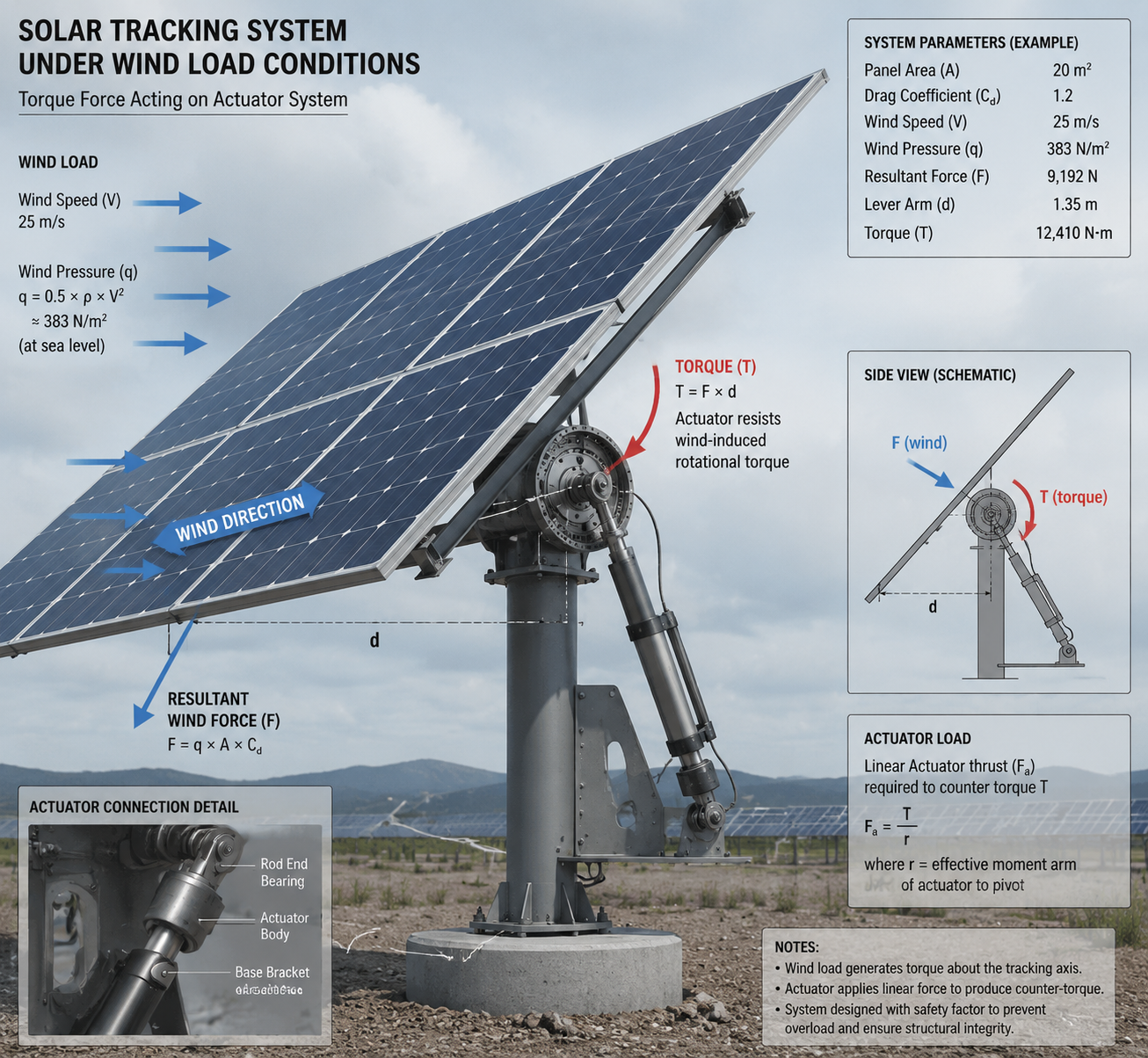
Wind Load Torque
Wind loading dominates the torque budget in most tracker designs. A standard engineering approach treats the panel array as a flat plate and estimates drag force based on panel area, wind pressure, and the distance from the pivot axis to the panel centroid. Dynamic wind pressure at 12 m/s is approximately 88 Pa; at 25 m/s survival speed it reaches 382 Pa. Applied to a 1.8m × 1.0m panel (1.8m² area) at worst-case incidence angle, drag force at 12 m/s is roughly 160 N and at 25 m/s approximately 688 N. With a typical pivot offset of 0.25m from the panel centroid, this produces 40 N·m at operating wind speed and 172 N·m at survival wind speed—before any safety margin.
This is where many first designs underestimate requirements. The motor doesn't just need to move the panel—it needs to hold it against peak gust loads while energized, and in some designs, while de-energized if the control system fails or loses power. Detent torque in a stepper is only 10–20% of holding torque, which is usually insufficient for wind stow conditions. Worm gearbox self-locking behavior is often relied upon here, and it works—but only if the worm gear ratio and lead angle are correctly specified for irreversibility. Lead angles below 5° are reliably self-locking; above 8°, do not assume self-locking under shock loads.
Panel Weight and Structure Inertia
Individual 60-cell monocrystalline panels (1.65m × 1.0m) weigh 18–22 kg including frame. A 4-panel single-axis array with aluminum extrusion mounting hardware and torque tube segment totals approximately 110–140 kg of rotating mass. At typical tracker pivot geometry, the rotational inertia of this assembly is 25–45 kg·m². At low tracking speeds this contributes negligible dynamic torque, but during stow operations at 3–5 RPM output shaft speed, acceleration torque can add 15–25% to the total load requirement.
Gearbox Ratio Selection
Typical NEMA 23 stepper motors produce 1.5–3.0 N·m holding torque. NEMA 34 motors reach 4–12 N·m depending on frame length and winding. To achieve 30–80 N·m at the structural pivot, gear ratios of 20:1 to 100:1 are common. Worm gearboxes in the 50:1 to 100:1 range are the most frequently used in single-axis utility trackers. The self-locking characteristic of worm gears (lead angles typically below 5°) provides passive position holding without motor power—an important feature for power outage scenarios and extended overcast periods where unnecessary motor energization wastes power and generates heat.Most OEM designers do not select based on peak torque alone, but on survival wind condition combined with gearbox self-locking behavior and long-term backlash stability.
Safety Factor
Apply a safety factor of 1.5× minimum on continuous operating torque; 2.0–2.5× is more appropriate for gust load and stow scenarios. Undersizing gearboxes to save cost is a reliable way to generate field failures. Worm gear tooth wear is the most common early-life failure in undersized solar tracker drives, typically presenting as backlash increase and positional drift after 2–4 years in high-wind sites.
Real Engineering Design Example
Consider a single-axis tracker with a 2-panel array: 1.8m × 1.0m panels, aluminum frame, total rotating mass approximately 35 kg, pivot offset 0.25m from array centroid. Design wind speed for normal operation: 12 m/s. Survival stow speed: 25 m/s.
Dynamic wind pressure at 12 m/s: q = 0.5 × 1.225 × 12² ≈ 88 Pa; at 25 m/s: q ≈ 382 Pa
Panel drag force at 12 m/s (1.8m² area, Cd ≈ 1.0): F ≈ 88 × 1.8 = 158 N
Operating pivot torque: 158 N × 0.25m offset = 39.5 N·m → round to ~40 N·m
Stow wind torque: 382 × 1.8 × 0.25 ≈ 172 N·m
With 2.0× safety factor on stow: required gearbox holding torque ≥ 344 N·m
Selected gearbox: 80:1 worm gearbox, output rated torque 400 N·m continuous, holding torque 920 N·m
Required motor holding torque (operating, 2.0× SF): (40 × 2.0) ÷ 80 ÷ 0.4 (worm efficiency) = 2.5 N·m
Selected motor: NEMA 23, 3.0 N·m holding torque, 57mm frame, 4.2A rated current
Driver: DM542T or equivalent, 4.2A peak, 1/8 microstepping, 50% hold current reduction
Tracking speed at 60 RPM motor: 60 ÷ 80 = 0.75 RPM output; 0.75 × 6 = 4.5°/min — sufficient for stow at ~6 minutes from 45° to 0°
This configuration provides adequate margin at operating conditions and survives stow loads through worm gear self-locking, with the motor de-energized during power outages. Normal tracking steps run at 10–15 RPM motor speed; the higher RPM capacity is reserved for stow operations.
Gearbox Selection in Solar Tracking Systems
Worm gearboxes dominate this application for their self-locking behavior, high single-stage ratio, and relatively low cost. The tradeoff is efficiency: worm gearboxes typically run at 35–50% mechanical efficiency at 80:1 ratio, dropping further at higher ratios due to friction losses in the worm-wheel mesh. For slow-speed, intermittent-duty solar tracking, this is acceptable—the motor energizes for only a few seconds per positioning cycle.
Slew drive units—which integrate a worm gear set with a slewing ring bearing—are increasingly used in larger tracker arrays. Field-sourced data from commonly available SDE-series slew drives gives a practical reference:
| Slew Drive Size (PV Tracker System Class) | Gear Ratio | Continuous Output Torque (N·m) | Peak Holding Torque (N·m) | Tilting Moment Capacity (kN·m) | Efficiency | Backlash / Accuracy | IP Rating | Operating Temperature | Self-locking Behavior | System Mass |
|---|---|---|---|---|---|---|---|---|---|---|
| 3" (76mm) Light OEM Tracker | 31:1 | 600 | 5,800 | 1.5 | ~40% | ≤0.15° | IP66 | -40°C to +80°C | Self-locking worm gear (non-backdrivable) | 25 kg |
| 5" (127mm) Small Single-Axis Tracker | 37:1 | 800 | 9,200 | 6.0 | ~40% | ≤0.15° | IP66 | -40°C to +80°C | Yes | 34 kg |
| 7" (178mm) Medium Utility Tracker | 57:1 | 2,000 | 13,200 | 7.5 | ~40% | ≤0.15° | IP66 | -40°C to +80°C | Yes | 56 kg |
| 9" (229mm) Utility Scale Tracker | 61:1 | 4,300 | 27,200 | 16.0 | ~40% | ≤0.15° | IP66 | -40°C to +80°C | Yes | 92 kg |
| 12" (305mm) Heavy Duty PV Array | 78:1 | 5,800 | 41,000 | 25.0 | ~40% | ≤0.15° | IP66 | -40°C to +80°C | Yes | 160 kg |
| 17" (432mm) Dual-Axis / CPV Systems | 102:1 | 9,460 | 53,040 | 67.0 | ~40% | ≤0.15° | IP66 | -40°C to +80°C | Yes | 320 kg |
For small OEM tracker designs with 1–4 panels, a 3" slew drive paired with a NEMA 34 stepper is a common and field-validated combination. For row-level single-axis trackers covering 20–40m² of panel area, 7"–9" slew drives are typical. The 17" and above sizes are used in large-format dual-axis CPV systems where module areas exceed 20m² per tracker head.
Planetary gearboxes offer higher efficiency (85–95%) and lower backlash, but they are not self-locking. This means a brake or secondary locking mechanism is required to hold position under wind load without continuous motor energization. For larger commercial trackers where actuator efficiency contributes to overall system cost, planetary gearboxes with electromagnetic brakes are used. For smaller OEM designs, the added cost and failure mode of a brake often tips the decision back toward worm gear.
Backlash specification matters. A worm gearbox with 0.5° of backlash at the output shaft translates directly to positional uncertainty in the panel angle. For ±1.0° tracking tolerance, this is borderline acceptable. Specifying reduced-backlash worm gearboxes (typically 0.1–0.3° output backlash) costs more but simplifies the control system and eliminates hunting behavior near the target position.
Driver and Controller Electrical Parameters
Driver selection is often treated as secondary to motor selection, but in outdoor installations it directly affects reliability. The following are practical reference parameters for drivers used in production tracker systems:
| Control Parameter (Solar Tracking System Level) | Typical Specification | Engineering Recommendation (PV Field Use) |
|---|---|---|
| Driver Bus Voltage | 24–48 VDC | 36–48 VDC recommended for NEMA 34 systems to maintain torque stability during stow and wind recovery cycles |
| Phase Current Setting | 1.0–8.0 A | Match motor rated current; overdriving increases thermal aging in sealed outdoor enclosures |
| Holding Current Reduction | 30–70% of run current | 40–50% recommended; worm gear self-locking reduces need for continuous full torque holding |
| Microstepping Mode | Full to 1/32 step | 1/8 microstepping standard for utility PV tracking; 1/16 reserved for CPV and precision dual-axis systems |
| Driver Thermal Limit | 0–50°C (electronics) | Enclosure must maintain ≤50°C internal temperature; field systems frequently exceed 70°C without thermal design |
| Protection Functions | OCP / OTP / SCP | Must include stable thermal shutdown behavior; low-cost drivers show degraded reliability under desert cycling |
| Step Pulse Frequency | 0–200 kHz | PV tracking typically operates below 5 kHz; higher bandwidth only required for stow or diagnostic motion modes |
One recurring field issue: controller enclosures painted black and mounted in direct sun regularly reach 70–80°C internal ambient, even with modest internal dissipation. Driver MOSFET junction temperatures at 50°C ambient are already near the edge of reliable long-term operation. Specifying white or light-colored enclosures for outdoor tracker controllers, or adding a small ventilation louver with a dust filter, extends driver MTBF significantly.
Environmental Challenges
Solar trackers operate in some of the harshest environments where precision motion systems are expected to function. Desert installations combine UV exposure, 60°C+ ambient temperatures, abrasive dust, and occasional rain. Coastal installations add salt spray corrosion. High-altitude sites introduce UV intensity and temperature cycling. Tropical installations present sustained humidity and biological fouling.
IP65 is the minimum acceptable rating for motor and gearbox enclosures in outdoor tracker applications. IP66 is preferred for sites with regular high-pressure washdown or driving rain. The slew drive table above shows IP66 as the production standard for commercially available units—this is the right baseline.
Shaft seals on gearboxes are a common failure point. Double-lip seals with grease packing outperform single-lip designs in field life, particularly where shaft oscillation rather than continuous rotation is the normal duty cycle.
Thermal cycling causes differential expansion between motor housing, mounting bracket, and gearbox body. Over thousands of cycles, this works fasteners loose and can cause alignment drift. Stainless fasteners with thread-locking compound are a practical standard; all-aluminum structural connections without galvanic isolation are a long-term corrosion risk in coastal environments.
Gearbox lubrication intervals depend heavily on operating temperature range. Most synthetic gear oils (ISO VG 220 class) maintain acceptable viscosity from -30°C to 100°C, but mineral oils can thicken significantly at low temperatures, causing startup torque spikes that exceed motor holding torque. In cold-climate installations, this is a real failure mode—overnight drops below -15°C cause lubricant to gel, and the first tracking move of the day stalls the motor. Specifying synthetic EP gear oil with a pour point below -40°C addresses this.
Re-lubrication intervals for worm gearboxes in outdoor solar applications: 2 years maximum in desert or high-UV environments; 3 years in temperate climates. Sealed lifetime-lubricated units are preferable where access for field maintenance is impractical.
Stepper Motor vs Servo in Solar Tracking
| Design Consideration | Stepper Motor System | Servo Motor System |
|---|---|---|
| Control Architecture | Open-loop pulse control; no feedback required for standard PV tracking systems | Closed-loop control using encoder or resolver feedback for continuous correction |
| Holding Strategy at Standstill | Stepper holding torque + worm gearbox self-locking (common in solar trackers) | Requires active torque control or mechanical brake to maintain position without power |
| System Cost | Low cost: ~$30–$120 (NEMA 23/34 system level) | Medium to high: ~$150–$500+ depending on encoder and drive configuration |
| Position Accuracy | ±0.3° to ±0.5° with 1/8 microstepping (sufficient for utility PV tracking) | ±0.05° to ±0.1° depending on encoder resolution and tuning quality |
| Maintenance Requirement | Low; gearbox inspection only, no encoder calibration required | Medium; encoder alignment and feedback diagnostics required |
| Overload Behavior | Possible step loss under extreme wind if torque margin is insufficient; requires homing recovery logic | No step loss; system triggers fault or compensates via feedback loop |
| Best Application | PV flat-panel trackers, AGV drives, packaging automation, light industrial motion systems | CPV systems, high-precision dual-axis trackers, semiconductor motion stages |
| Field Engineering Insight | Widely deployed in Southeast Asia and Middle East utility PV projects due to simplicity and cost efficiency | Used where tracking error directly impacts energy yield or process accuracy |
Servos make sense in concentrated photovoltaic (CPV) systems where tracking accuracy requirements are ±0.1° or tighter, and where the premium for closed-loop control is justified by yield sensitivity. For standard flat-panel trackers, the accuracy advantage of servo over a properly sized stepper with microstepping is marginal relative to cost difference.
Common Failure Modes in Solar Tracking Motors
Field experience across multiple tracker deployments produces a consistent list of failure modes:
Worm gear tooth wear from sustained wind loading at undersized torque margins — presents as gradual backlash increase, typically caught only during annual maintenance or after a noticeable yield drop after 2–4 years
Moisture ingress through degraded shaft seals, leading to winding insulation breakdown or bearing corrosion; most common 5–8 years into service as EPDM or NBR seal materials age and harden
Step loss under wind gust events when motor hold current is reduced to 40%; the motor loses magnetic lock under instantaneous torque spikes exceeding holding torque — recoverable only if the controller runs a homing routine after the event
Connector corrosion at motor wiring terminations; outdoor M12 connectors without adequate potting or overmolding are a frequent nuisance failure source — specify IP67-rated connectors with gold-plated contacts in coastal or tropical deployments
Thermal cycling fatigue at motor mounting points on aluminum extrusion frames; stainless bolt into aluminum without isolation washer causes accelerated galvanic corrosion within 3–5 years in coastal sites
Driver MOSFET failure from inadequate thermal management in field controller enclosures; black enclosures in direct sun reach 70–80°C internal temperatures, pushing junction temperatures beyond rated limits and causing early MOSFET degradation
OEM Design Guidelines
For OEM manufacturers developing a solar tracker drive system, the following represent practical design standards based on field performance rather than datasheet optimization:
Frame size: NEMA 23 (57mm) is appropriate for single-panel and 2-panel arrays with 50:1–100:1 gearboxes; NEMA 34 (86mm) for 4-panel arrays or where gearbox ratio must be kept below 50:1 for dynamic stow response
Torque margin: size gearbox output torque at 2.0× calculated peak wind load at operating speed; stow load should be within gearbox holding torque rating without motor assistance
Driver current reduction: 40–50% of rated run current at hold is appropriate; full hold current is unnecessary given worm gear self-locking and continuous full-current energization shortens winding insulation life in high ambient temperature environments
Microstepping: 1/8 step is the practical minimum for smooth motion without resonance; full-step operation in the 5–30 RPM motor speed range produces audible vibration and mechanical wear at the gearbox input shaft
Homing cycle: implement a mandatory homing routine at startup and at minimum once per 24-hour cycle; limit switches should be IP67 rated, mounted with debris-deflecting guards, and specified for at least 500,000 mechanical cycles
Cable management: allow 20–30% extra cable loop length at rotating joints for the full angular travel range; account for thermal contraction at -20°C — PVC-jacketed cable stiffens considerably and can pull connectors loose in cold climates; use PUR-jacketed cable for outdoor moving installations
Lubrication: specify re-lubrication intervals of 2 years maximum for worm gearboxes; document this in the maintenance manual — field experience shows this is the most commonly skipped maintenance item and the most common cause of gearbox failure at year 5–7
Conclusion
Stepper motors are a practical and cost-effective choice for solar tracking drive systems when sized correctly and protected against the environmental conditions of the installation site. The failure cases in this application are well-understood: undermargined gearboxes, inadequate sealing, and thermal management problems in drivers and controllers account for the majority of field issues. Addressing these systematically at the design stage — using realistic wind load calculations, appropriate safety factors, IP66-rated components, and synthetic lubricants specified for the site temperature range — produces drive systems that meet 20-year service life expectations without the cost premium of servo-based alternatives. Motor and gearbox selection follows from getting the torque budget right first; everything else is implementation detail.
Frequently Asked Questions (FAQ)
Can stepper motors handle high wind loads in solar tracking systems?
Yes, stepper motors can handle high wind loads when properly sized with a suitable gearbox. In most industrial solar tracker designs, the motor itself is not responsible for resisting wind load directly. Instead, torque is multiplied through worm or planetary gearboxes, which provide the required holding force. Proper safety factor (typically 2.0× or higher) is essential to ensure reliability under gust conditions.
Why are worm gearboxes preferred in solar tracking applications?
Worm gearboxes are widely used because of their high reduction ratios, compact structure, and self-locking characteristics. Self-locking allows the system to hold panel position without continuous motor energization, reducing energy consumption and improving safety during power loss conditions. However, efficiency is lower compared to planetary gearboxes, which is acceptable in low-speed, intermittent-duty applications such as solar tracking.
OEM Inquiry & Custom Stepper Motor Solutions
HDBMotor provides stepper motor and gearbox integration solutions for solar tracking systems, including NEMA 23 and NEMA 34 configurations with customized torque, protection level, and gearbox ratios for different environmental conditions.
For OEM projects, we support application-based motor sizing, gearbox matching, and driver selection based on real wind load and duty cycle requirements rather than catalog-only specifications.
If you are developing a solar tracking system or need a customized motion solution, you can contact our engineering team for application-level evaluation and configuration support.
Contact: [email protected]