
 Deutsch
 한국어
한국어
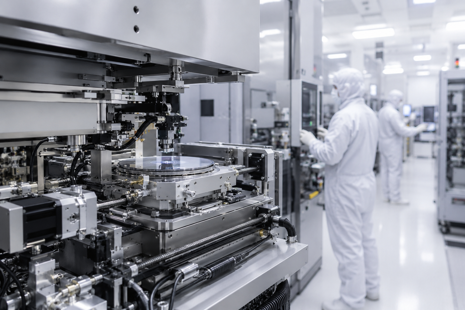
HDBMotor supplies precision stepper motors for semiconductor equipment OEM applications including wafer handling systems, semiconductor test equipment, optical alignment stages, and cleanroom automation platforms. Our cleanroom-compatible stepper motor solutions are available with 0.9° step angle configurations, grease-free bearing options, PTFE cable assemblies, and CE/RoHS compliant materials for ISO Class 5 semiconductor environments.
Specifying a precision stepper motor for semiconductor equipment is a different exercise than sourcing for a general industrial application. The cleanroom environment changes almost every parameter that matters — materials, lubrication, cable jacketing, particle generation from motor operation itself. OEM machine builders working on wafer handling systems, optical alignment stages, or semiconductor test equipment often spend more time on material compatibility documentation than on the motor selection itself.
Stepper motors are still widely used in semiconductor automation, particularly for auxiliary positioning axes that don't require the dynamic response of a full servo system. They're not the right choice for everything, and experienced engineers know where that boundary is. But for applications requiring sub-millimeter repeatability at moderate speeds, with limited cable routing space and strict contamination requirements, a well-specified stepper motor is often more practical than the servo alternative.
This article covers what actually matters when selecting a cleanroom-grade stepper motor for semiconductor equipment — the specifications, the tradeoffs, the things that get overlooked during procurement, and where customization from an OEM supplier makes a real difference.
Motion Control Challenges in Semiconductor Equipment
The motion requirements in semiconductor equipment are demanding in ways that don't always show up clearly in a motor datasheet. Positioning repeatability in wafer transport systems is often specified in microns, which places strict requirements on backlash, motor resolution, and driver tuning. A 1.8° full-step stepper motor with basic microstepping will hit those numbers in many cases — but not all. The difference between a motor that works in a test bench and one that works consistently over 18-hour production cycles in a Class 5 cleanroom is significant.
Contamination control is probably the most underestimated challenge in semiconductor motion system design. Standard stepper motors use petroleum-based grease in their bearings and sometimes molybdenum disulfide in the rotor assembly. Both can outgas in cleanroom environments, and both can generate particulate contamination under mechanical load cycling. The consequences aren't just a failed certification audit — particle contamination during wafer transport can affect yield in ways that take weeks to diagnose properly.
Vibration is another factor that matters more than many buyers expect. Stepper motors generate torque in discrete pulses rather than continuously — that's fundamental to how they work. At low speeds, this creates vibration that can affect sensitive positioning systems. On a wafer transport arm or an optical alignment stage, vibration during positioning affects repeatability in ways that don't show up during static testing. It shows up during actual wafer handling under production conditions.
Uptime requirements in semiconductor fabs are severe. A motion system failure that causes a production line stoppage is not a minor maintenance event — it affects yield on wafers already in process, and the cost of that is substantially higher than the cost of the motor itself. This creates pressure toward over-specifying motors, which is understandable, but it also means that maintenance-related considerations — bearing life, thermal cycling effects on winding insulation, connector durability — should be part of the selection process, not an afterthought.
Why 0.9° Step Angle Matters in Semiconductor Applications
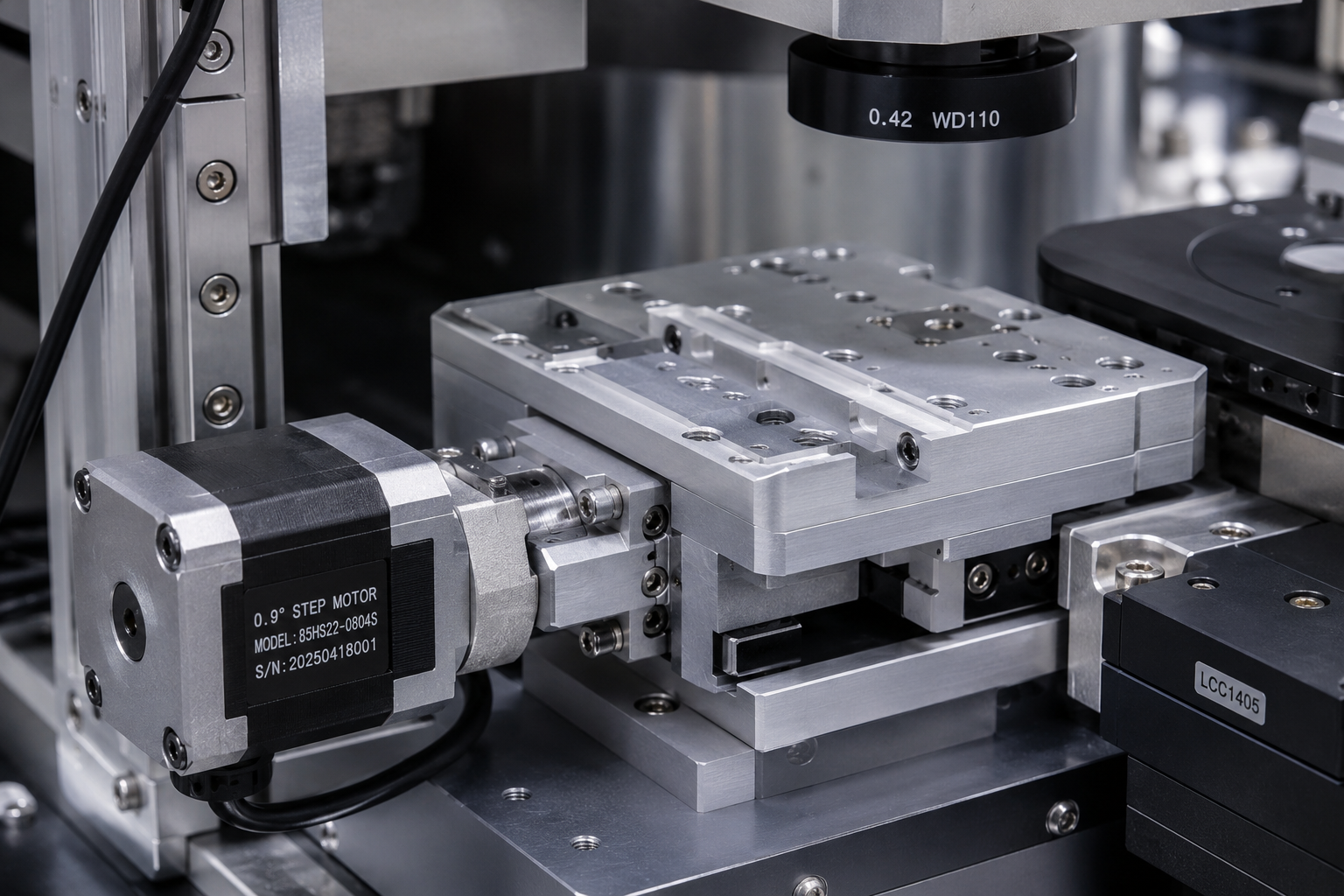
Most industrial stepper motors use a 1.8° step angle — 200 full steps per revolution. A 0.9° motor doubles that to 400 full steps per revolution. On paper, this halves the step error per full step, which improves positioning resolution in open-loop systems. In practice, the benefits go beyond just resolution.
At low speeds — the kind of speeds used in wafer transport approaches and optical stage positioning — a 400-step motor runs considerably smoother than a 200-step motor at equivalent microstepping ratios. The torque ripple is lower, the vibration signature is smaller, and the mechanical resonance behavior is different. The fundamental resonance frequency of a 0.9° motor is higher than the equivalent 1.8° motor, which means it's less likely to coincide with the natural frequencies of the mechanical structure being driven. In semiconductor equipment, where the structure is often a lightweight aluminum gantry or a thin-arm wafer transport mechanism, resonance avoidance is a real design concern.
Microstepping reduces vibration further but introduces its own limitations. This is one of the most misunderstood topics in stepper motor selection. A stepper motor running at 1/16 microstepping does not actually position in 1/16 of a full step with consistent accuracy — the intermediate positions have varying torque levels and positional error. Microstepping improves smoothness and reduces resonance, but for precision positioning, you're ultimately relying on the full-step positions for reliable accuracy. A 0.9° motor at 1/8 microstepping provides smoother motion and more usable intermediate positions than a 1.8° motor at 1/16 microstepping, with less positional uncertainty at each step.
For wafer handling applications specifically, the low-speed smoothness of a 0.9° motor matters during the deceleration approach to pick-and-place positions. Vibration during the final approach — even sub-millimeter vibration — can cause wafer positional error that only shows up after the gripper has released. This is difficult to diagnose and easy to overlook if the motor selection decision is made purely on torque and cost criteria.
Cleanroom Compatibility Specifications
Cleanroom Material Selection
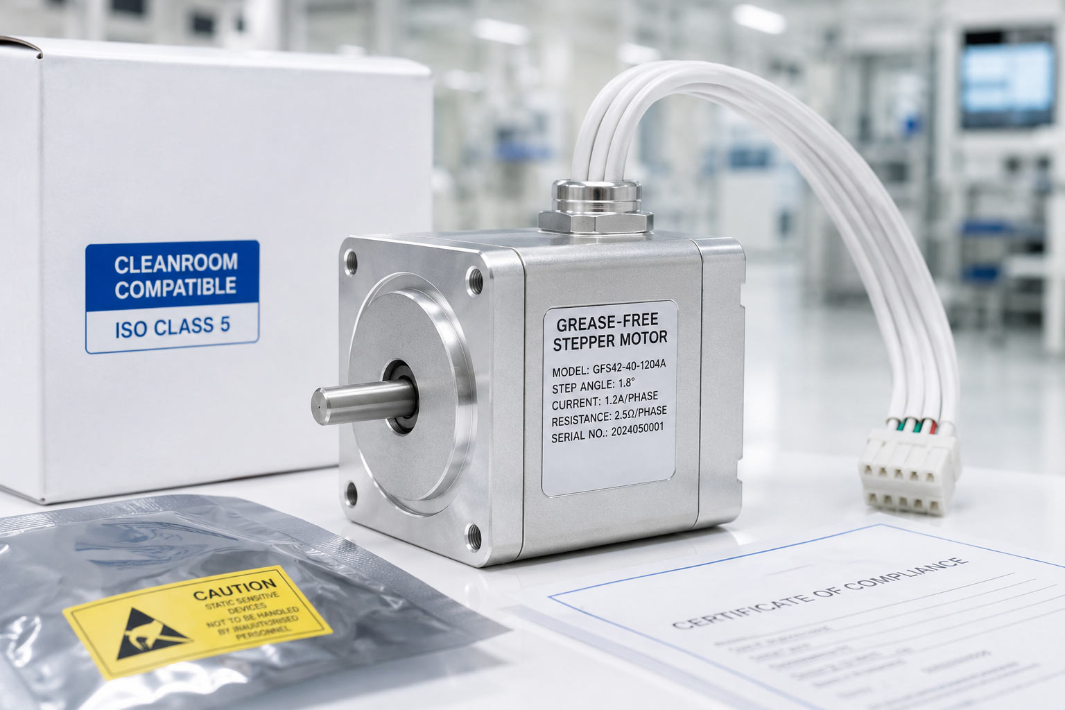
The motor housing material matters. Standard stepper motors use cold-rolled steel end caps with standard paint or zinc plating. Both can generate particles under mechanical stress and thermal cycling. For cleanroom applications, anodized aluminum end caps and stainless steel shafts are the appropriate starting point. Anodized aluminum is particle-stable under normal operating conditions and resists outgassing. Hard anodizing provides additional durability where the motor is subject to handling during maintenance.
Stainless steel shafts are more corrosion-resistant than the standard carbon steel shafts used in most catalog motors. In cleanroom environments with controlled humidity, this matters less than in chemical-adjacent cleanroom zones where trace process chemicals can cause corrosion on standard steel surfaces. If your application is in a wet etch area or near solvent exposure, this needs to be specified explicitly.
Cable jacketing is a detail that gets overlooked surprisingly often. Standard PVC cable jackets can outgas plasticizers over time, particularly in elevated temperature environments. PTFE jacketed cables are the appropriate choice for cleanroom installations — PTFE is stable, non-outgassing, and compatible with most cleaning agents used in fab environments. The connector itself needs to be specified as well; standard plastic connector housings may not be compatible with cleanroom cleaning protocols.
Grease-Free Bearing Options
This is probably the most critical cleanroom specification for stepper motors, and it's often the one that distinguishes a genuinely cleanroom-compatible motor from a standard motor that's been relabeled. Standard ball bearings use petroleum-based grease or oil as a lubricant. Both outgas measurably in controlled environments, and both can generate contaminating particles as the lubricant breaks down under load cycling.
Grease-free bearings for cleanroom applications use dry lubricants — typically PFPE-based (perfluoropolyether) dry film lubricants or ceramic ball bearings with no lubricant at all. PFPE lubricants are non-outgassing and compatible with ISO Class 5 environments. Ceramic bearings with no lubrication are suitable for applications with lower radial loads and moderate duty cycles.
The tradeoff is bearing life. Grease-free bearings generally have shorter service life than properly lubricated standard bearings under the same loading conditions. In high-cycle applications — thousands of cycles per day — this needs to be planned for in the maintenance schedule. The bearing life reduction is real, but for most semiconductor automation applications running at moderate speeds and loads, grease-free bearings provide acceptable service intervals. What's not acceptable is discovering this limitation after a failed contamination audit has caused a production shutdown.
Low Vibration Design Considerations
Vibration in stepper motors has multiple sources: the fundamental step torque pulse, rotor-stator magnetic reluctance variation, mechanical resonance of the rotor mass and shaft, and bearing noise. In cleanroom semiconductor applications, each of these matters both for positioning accuracy and for particle generation.
Bearing noise generates particles. A motor with worn or poorly manufactured bearings will generate more particulate than a properly specified cleanroom motor. This isn't just about contamination from outgassing — it's about mechanical wear particles from bearing surfaces. ISO Class 5 environments require particle counts below specific thresholds, and a degraded motor bearing can push a zone out of compliance.
Resonance suppression in the driver is partially effective. Modern stepper drives with anti-resonance algorithms can reduce vibration substantially in the mid-speed range. But driver compensation doesn't fully replace good motor design. A motor with a well-balanced rotor and smooth magnetic circuit will always outperform a motor with a driver trying to compensate for its mechanical deficiencies. When sourcing for semiconductor equipment, the motor itself should have low resonance characteristics — the driver tuning is a supplement, not a substitute.
Stepper Motor vs Servo Motor for Semiconductor Equipment
This comparison is worth doing honestly, because the answer isn't always stepper motors. Semiconductor equipment uses both, and the choice depends on the specific axis requirements.
| Evaluation Factor | Precision Stepper Motor | Servo Motor |
|---|---|---|
| Typical Semiconductor Usage | Wafer handling support axes, cassette shuttles, optical positioning, auxiliary motion systems | Primary wafer transport axes, high-speed gantries, lithography positioning stages |
| Positioning Method | Open-loop by default; optional encoder feedback available | Closed-loop with continuous encoder feedback |
| Positioning Resolution | 0.9° motors provide 400 full steps/rev; higher effective resolution with microstepping | Dependent on encoder count and servo tuning parameters |
| Low-Speed Stability | Very good with 0.9° step angle and anti-resonance driver control | Excellent smoothness across full speed range |
| High-Speed Dynamic Performance | Limited at high RPM due to torque drop-off | Superior acceleration and high-speed torque retention |
| Vibration Characteristics | Requires proper microstepping and resonance suppression tuning | Typically lower vibration under dynamic motion conditions |
| System Complexity | Simpler wiring and commissioning; fewer control parameters | More complex integration with encoder tuning and feedback configuration |
| Risk of Position Loss | Possible under overload conditions in open-loop operation | Closed-loop feedback continuously corrects positioning error |
| Cleanroom Configuration Availability | Available with grease-free bearings, PTFE cable, anodized housing, low-outgassing materials | Available but typically at higher system cost |
| Cost Efficiency for Multi-Axis Equipment | Highly cost-effective for medium-precision semiconductor automation | Higher overall system cost, especially in multi-axis architectures |
| Recommended Semiconductor Applications | ATE systems, wafer cassette handling, inspection stages, auxiliary positioning axes | High-speed wafer stages, precision lithography motion, dynamic transport systems |
In practice, many semiconductor machines use servo motors on their primary wafer transport and process axes and stepper motors on auxiliary positioning, door actuation, magazine shuttle, and sensor positioning axes. This hybrid approach balances cost and performance appropriately. Specifying servo motors across all axes is technically defensible but often economically inefficient for the motion requirements of auxiliary axes.
Technical Specifications
| Technical Parameter | Available Configuration | Semiconductor Application Notes |
|---|---|---|
| Step Angle | 0.9° / 1.8° | 0.9° configurations are commonly selected for wafer handling, optical alignment, and precision positioning stages |
| Motor Frame Size | NEMA 11 / NEMA 17 / NEMA 23 | NEMA 11 for compact instrument motion; NEMA 23 for higher-load transport and gantry systems |
| Holding Torque Range | 0.05 Nm – 3.0 Nm | Selection depends on payload inertia, acceleration profile, and positioning stability requirements |
| Operating Voltage | 2V – 48V winding options | Custom winding configurations available to match semiconductor equipment driver architecture |
| Phase Current | 0.4A – 4.5A | Thermal evaluation recommended for enclosed cleanroom equipment with limited airflow |
| Positioning Method | Open-loop / Closed-loop with encoder | Closed-loop configurations recommended for high-cycle positioning axes with overload risk |
| Encoder Options | Incremental 100–10,000 PPR / Absolute encoder | Encoder integration supports position verification and motion recovery after power interruption |
| Bearing Configuration | Standard grease / PFPE dry lubricant / Grease-free ceramic bearing | Grease-free options available for ISO Class 5 cleanroom compatibility |
| Shaft Material | Carbon steel / 304 stainless steel | Stainless steel shafts recommended for chemically sensitive semiconductor environments |
| Housing Material | Cold-rolled steel / Anodized aluminum | Anodized aluminum improves corrosion resistance and minimizes particle generation risk |
| Cable Jacket Material | PVC / Low-outgassing PTFE | PTFE cable assemblies are preferred for cleanroom semiconductor equipment and vacuum-adjacent applications |
| Connector Configuration | JST / Molex / Amphenol / Flying leads | Custom cable exit direction and connector orientation available for space-constrained equipment layouts |
| Ingress Protection | IP40 / IP54 | IP54 sealing recommended for equipment operating near wet process zones |
| Insulation Class | Class B (130°C) / Class F (155°C) | Class F insulation preferred for continuous-duty semiconductor automation systems |
| Compliance Standards | CE / RoHS 3 / REACH | Compliance documentation and material declarations available for OEM qualification audits |
| Customization Support | Shaft machining / winding modification / encoder integration / cable customization | Suitable for low-volume semiconductor OEM projects and custom automation platforms |
Certifications and Compliance Documentation
Semiconductor equipment procurement involves a level of compliance documentation that goes beyond most industrial sectors. CE marking and RoHS compliance are baseline expectations — they're rarely the limiting factor in semiconductor supplier qualification. REACH compliance and full material declarations are more commonly the documentation bottleneck.
REACH compliance documentation means providing a full list of substances of very high concern (SVHC) present in the motor above 0.1% by weight. For a motor assembly, this includes the winding wire insulation, bearing lubricant, cable jacket material, connector housing, and any plating or surface treatments. Generating this documentation requires knowing your full supply chain for those components, which not all motor manufacturers have visibility into.
RoHS 3 compliance (EU Directive 2015/863) restricts ten substances including lead, mercury, cadmium, and specific phthalates. Standard motor components are generally compliant, but the connector and cable assembly can introduce non-compliant plasticizers in PVC jacketing — which is one of several reasons PTFE cable is preferred for cleanroom semiconductor applications beyond just outgassing concerns.
Semiconductor OEM customers frequently require lot-level traceability documentation, material certifications from component suppliers, and test reports for each production batch. This is not unusual for the industry, but it needs to be established as a requirement during the initial RFQ process rather than requested after production has started. Suppliers who don't normally provide this documentation can usually generate it, but it takes time to build the traceability process if it wasn't designed in from the beginning.
For equipment exported to North American markets, UL component recognition may be required depending on how the equipment is certified. This needs to be discussed during the motor specification stage — it affects which motor configurations are available and may affect lead time.
Manufacturing Considerations for Semiconductor OEM Projects
Manufacturing motion components for semiconductor equipment is not only about meeting electrical specifications. In many projects, the manufacturing process itself becomes part of the qualification review. Semiconductor OEM customers typically evaluate not just torque curves and dimensional tolerances, but also material traceability, assembly handling procedures, packaging methods, and consistency between production batches.
This becomes especially important for equipment operating in cleanroom environments where particulate contamination, outgassing behavior, and long-term repeatability are critical to system reliability. A motor that performs well mechanically can still become a qualification problem if the manufacturing process lacks traceability or clean handling controls.
For cleanroom-compatible stepper motor production, assembly handling procedures are usually stricter than for standard industrial motors. Components such as bearings, shafts, rotor assemblies, and cable sets should be handled in controlled assembly areas to reduce contamination risk before final packaging. In practice, contamination introduced during assembly is often harder to eliminate than contamination introduced during shipping.
Material consistency is another area semiconductor OEM teams pay close attention to. Even small changes in cable insulation compounds, connector housing materials, or lubricant suppliers can trigger requalification requirements on the customer side. Because of this, incoming material traceability becomes an important part of semiconductor motor manufacturing.
For example, winding wire insulation grades, PTFE cable materials, bearing lubricants, and anodizing treatments are typically sourced with batch tracking documentation. This allows the manufacturer to trace production lots back to individual material suppliers if a compliance or reliability issue needs investigation later. Some semiconductor equipment manufacturers also request lot-level production records during supplier audits, particularly for equipment exported to North America, Europe, or Japan.
Winding inspection is another manufacturing detail that matters more in semiconductor applications than in general automation equipment. Variations in winding resistance, insulation quality, or coil tension can affect thermal stability and vibration behavior during continuous operation. In high-duty-cycle semiconductor equipment running 24-hour production schedules, these small inconsistencies become more visible over time.
Because of this, production inspection for semiconductor-oriented stepper motors often includes resistance consistency checks between phases, insulation withstand testing, and thermal verification under controlled load conditions. These tests are not unique to semiconductor motors, but the acceptable process variation is usually tighter than in standard industrial applications.
Shaft concentricity inspection is equally important for precision positioning systems. Wafer handling arms, optical stages, and semiconductor gantry platforms are sensitive to rotational eccentricity because even small shaft runout can amplify vibration at the mechanical structure level. A motor with acceptable torque output may still create positioning instability if shaft concentricity is inconsistent.
In practice, concentricity inspection becomes particularly important for motors using custom shafts, extended shafts, or integrated pulleys. Semiconductor OEM projects frequently require non-standard shaft machining, and maintaining alignment tolerances after machining is part of the manufacturing challenge. This is one reason why some low-cost catalog motors perform inconsistently once customized for actual equipment integration.
Packaging methods are also different for semiconductor-related shipments. Standard industrial carton packaging is often insufficient for cleanroom-compatible components. Dedicated packaging options may include sealed anti-contamination bags, desiccant protection, foam isolation for shaft protection, and individual lot labeling for traceability. For overseas OEM shipments, protecting the motor from corrosion during sea freight transit is another consideration, especially for motors using stainless steel shafts and cleanroom-rated surface finishes.
One detail that gets overlooked surprisingly often is storage time before installation. Semiconductor equipment projects sometimes involve long machine build cycles, meaning motors may remain in storage for several months before final integration. Packaging design therefore needs to consider humidity stability, corrosion protection, and connector protection during extended storage periods.
For low-volume semiconductor OEM projects, manufacturing flexibility is usually more important than production scale alone. Many semiconductor machine builders require relatively small quantities with highly specific mechanical or compliance requirements. In these situations, the supplier's ability to support customization, maintain documentation consistency, and communicate engineering changes clearly is often more valuable than simply offering the lowest catalog price.
OEM Customization Capabilities
The standard catalog motor rarely fits a semiconductor equipment design without at least one modification. Shaft length, connector type, cable exit direction — these are the common ones, and they're straightforward. More involved customizations are also possible but need realistic planning.One mistake OEM teams make is selecting the motor based only on holding torque while ignoring resonance behavior during low-speed positioning.
Shaft modifications are the most common request. A D-flat or keyway on an existing shaft is quick machining work. A custom shaft diameter — particularly going outside the standard range for a given frame size — requires confirmation that the bearing bore can accommodate it without new tooling. Stainless steel shaft material is a simple material specification change on most frame sizes.
Custom winding voltage affects the motor's resistance-inductance profile and needs to be evaluated against your driver's bus voltage and switching characteristics. A motor rewound to higher resistance for a 48V bus will have different thermal behavior than the catalog version, which means the operating thermal limits need re-evaluation. Some OEM customers come with a specific bus voltage and current limit from their driver, and working backward to the winding specification is a reasonable engineering process — but it takes a few iterations to confirm if it's outside the standard range.
Encoder integration on a standard stepper motor body adds axial length. The amount depends on the encoder disk diameter and housing design, but 20–35mm is typical. For equipment where the motor pocket has a fixed depth, this needs to be accounted for before finalizing the installation envelope. Absolute encoder options are available on selected frame sizes; if your application requires power-loss position retention, this needs to be specified early because it changes the motor configuration and driver interface requirements.
Low-to-mid volume OEM projects are a normal part of the work. Not every semiconductor equipment manufacturer is buying thousands of motors per year. Some are building 20–50 machines annually, or building a specialized instrument at even lower volume. Customization economics work differently at those volumes — tooling costs need to be discussed honestly, and some modifications that are trivial at high volume become cost-significant at low volume. The practical approach is to discuss your annual volume expectation during the initial technical conversation so that the customization recommendation accounts for it.
Semiconductor Equipment Application Scenarios
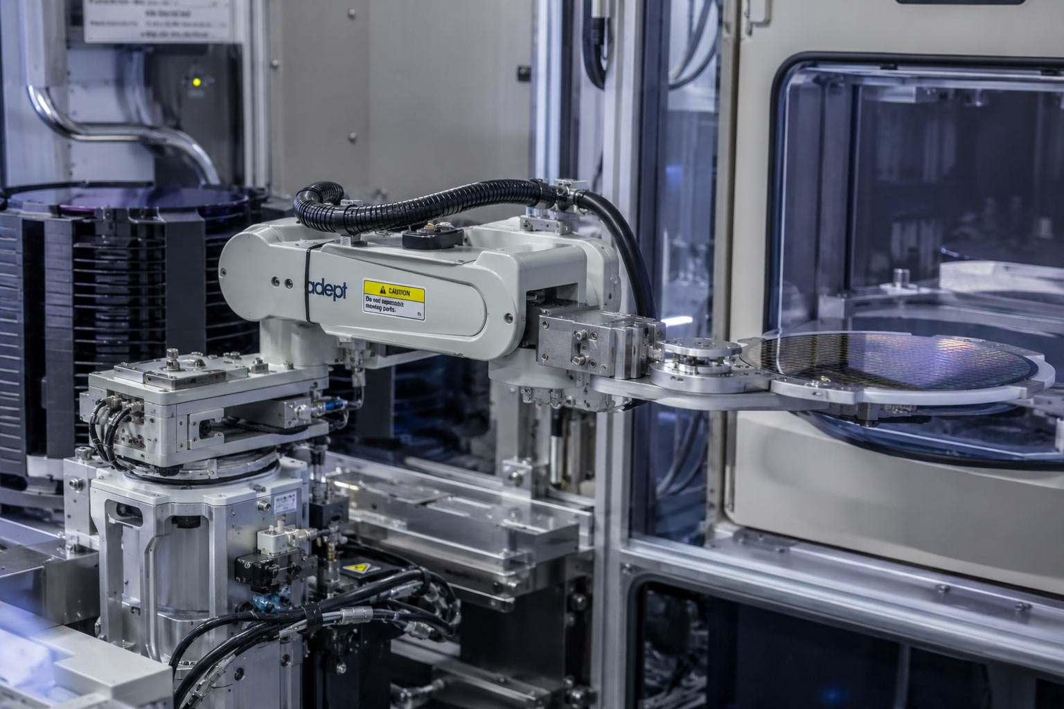
Wafer handling systems are the most demanding application on this list. Wafer transport arms, cassette elevators, and edge-grip transfer mechanisms require sub-millimeter positioning repeatability with extremely low vibration during approach and placement. The motor's mechanical signature — resonance behavior, step smoothness, bearing noise — directly affects transport reliability. A 0.9° motor with grease-free bearings and a cleanroom-rated cable assembly is the starting specification for this type of application.
Semiconductor test equipment typically uses stepper motors for probe card positioning, handler indexing, and tray transport. These applications tend to have moderate positioning requirements relative to wafer handling, but cycle counts are high. A probe station running 24 hours per day in a production test environment puts significant stress on bearing systems — both mechanically and thermally. Bearing life at that duty cycle needs to be calculated against the specific loading conditions, not assumed from datasheet ratings.
Optical alignment stages are where the 0.9° step angle and good microstepping behavior matter most. Alignment of optical components in lithography support equipment, inspection systems, and metrology tools requires fine, smooth motion at very low speeds. Resonance at the natural frequency of the stage structure can corrupt measurements. The motor selection in these applications often starts with vibration requirements rather than torque requirements.
Pick-and-place systems in semiconductor packaging equipment use stepper motors for Z-axis positioning, θ-axis rotation, and tool changing mechanisms. Cleanroom-compatible construction matters here because packaging equipment often operates in Class 7 or Class 8 environments where contamination standards, while less demanding than wafer fab environments, still rule out standard petroleum-lubricated motors.
Gantry positioning systems for inspection, dispensing, or marking use stepper motors on individual axes where the speed requirements are moderate and the cost of a full servo system per axis is not justified. A linear gantry with three controlled axes at moderate speed is a practical stepper application. The same gantry operated at high speed with dynamic payload changes would require servo.
Magazine shuttle and cassette handling systems are often overlooked when discussing semiconductor motion control, but they represent a large installed base of stepper motors in actual fabs. These systems move wafer cassettes between process tools, and while the positioning requirements are not as tight as wafer transport inside a tool, the cleanroom requirements are identical. The motor running a cassette shuttle elevator in a Class 5 fab needs the same material specification as the motor inside the process tool itself.
FAQ
What step angle is recommended for wafer handling stepper motor applications?
0.9° is the preferred starting point for semiconductor wafer transport and precision positioning axes. The lower step angle provides higher resolution, smoother low-speed operation, and a higher fundamental resonance frequency compared to 1.8° motors at equivalent microstepping ratios. For less demanding auxiliary axes — door actuation, cassette transport, sensor positioning — 1.8° may be adequate and is more widely available in cleanroom-specified configurations.
What does "grease-free" actually mean for a cleanroom stepper motor?
It means the bearings are lubricated with a dry lubricant — typically a PFPE-based dry film — or use ceramic balls with no lubricant. Standard petroleum-based bearing grease is replaced. The result is a motor that doesn't outgas hydrocarbon contamination and generates significantly less particulate from lubricant breakdown. Grease-free bearings generally have different load and life ratings than standard bearings under the same conditions — this needs to be accounted for in the maintenance planning.
Can a standard stepper motor be used in an ISO Class 5 cleanroom if I clean it first?
Not reliably. The issue isn't surface contamination — it's ongoing particle generation from bearing lubrication, cable jacket outgassing, and motor operation over time. A standard motor cleaned before installation will begin generating contamination during operation. The cleanroom specification needs to address materials, not just initial cleanliness.
Do I need a closed-loop (encoder) stepper system for semiconductor equipment?
In many cases, it depends on the application. Many semiconductor auxiliary axes operate reliably in open-loop mode with a properly sized motor — meaning the motor is loaded well within its torque rating so step loss under normal operation is not a realistic concern. Closed-loop operation with encoder feedback adds reliability for applications where overload or resonance-induced step loss is a genuine risk, or where position confirmation after motion is required by the equipment control logic. The encoder adds axial length and cost; it's appropriate where the application warrants it, not as a universal specification.
What REACH documentation is typically required for semiconductor OEM procurement?
At minimum, SVHC declaration confirming whether any substances on the current REACH Candidate List are present above 0.1% by weight in the motor assembly. Most semiconductor OEM customers also require a full material declaration (FMD) identifying all materials present in the product by component. Some customers require IPC-1752A format; others have their own documentation templates. Specify the required format during the RFQ process — converting between formats after the fact adds unnecessary time to the qualification process.
What is the typical lead time for a custom cleanroom stepper motor?
For modifications to existing motor configurations — shaft material change, PTFE cable substitution, connector change — lead time on samples is typically 15–20 working days. For winding modifications or configurations requiring new component qualification, 20–30 working days is more realistic. If your project involves new documentation requirements (specific test protocols, material certifications from sub-suppliers), build additional time into the schedule for the documentation process itself. Production lead time after sample approval is generally 30–45 working days at low-to-mid volume.
Is a stepper motor or servo motor better for a wafer transport arm?
This depends on the transport speed, positioning requirements, and whether position confirmation is required by the equipment control architecture. For slow-approach, precision-placement transport arms where speed is secondary to accuracy and vibration control, a well-specified 0.9° stepper with microstepping and anti-resonance driver features is a reasonable choice. For faster transport with dynamic position feedback requirements, servo is the appropriate technology. Many equipment architects use servo for the primary wafer transport axis and stepper motors for the supporting axes (Z-axis, θ-axis) where the motion profile allows it.
Are standard industrial connectors acceptable in ISO Class 5 areas?
This depends on the specific cleaning protocols used in the facility. Amphenol circular connectors with stainless steel shells and PTFE-sealed contacts are commonly used in semiconductor equipment. JST and Molex connector families can be used in Class 7 and Class 8 environments. For Class 5 areas, the connector housing material and sealing method should be reviewed against your facility's chemical exposure and cleaning requirements. This is worth confirming with your facilities team before finalizing the connector specification.
Working With HDBMotor for Semiconductor Motion Projects
HDBMotor is a motion control manufacturer, not a large catalog distributor. The distinction matters for semiconductor OEM projects because catalog suppliers are generally not set up to handle the documentation requirements, material specifications, or configuration modifications that semiconductor equipment procurement involves.
The work we typically do with semiconductor OEM customers starts with a technical discussion about the specific axis requirements — not a catalog quote. What is the positioning accuracy requirement? What is the duty cycle? What is the installation envelope? What documentation does your quality team need for supplier qualification? Getting these questions answered first avoids the situation where a motor gets specified, sampled, and then rejected during procurement qualification because the compliance documentation doesn't match your customer's requirements.
Our OEM program is built around low-to-mid volume projects. If you're building 30 units per year of a specialized semiconductor instrument and you need a cleanroom-rated motor with a specific shaft configuration, PTFE cable, and REACH documentation package, that's a project we can work with. We're not the right supplier for someone who needs to buy 10,000 motors per month from a regional warehouse. For OEM machine builders who need engineering engagement, custom configurations, and documentation support, we can provide that.
The honest limitations: we don't have a physical office in every market, so on-site commissioning support is not something we typically provide directly. Remote technical support is effective for most motor selection and integration questions, but if your team needs someone on-site for system commissioning, that typically involves your local integrator. Our production is based in China, which means import lead times need to be built into your project schedule — this isn't unusual for the motor supply chain, but it's worth planning for rather than discovering late in a project timeline.
Typical Information Included in a Semiconductor Motor RFQ
To speed up technical evaluation and avoid delays during qualification, semiconductor OEM teams usually include the following information when requesting a precision stepper motor quotation:
Required positioning accuracy — repeatability targets, allowable positioning error, and motion resolution requirements
Cleanroom classification — ISO Class 5 / Class 100, Class 7, or other environmental specifications
Cable exit direction — rear exit, side exit, connector orientation, and cable length requirements
Duty cycle — operating hours per day, continuous vs intermittent operation, acceleration profile, and load conditions
Required compliance documents — CE, RoHS, REACH, SVHC declaration, material traceability, or customer-specific qualification forms
Driver voltage and current limitations — available bus voltage, current limits, microstepping configuration, and driver model information
Installation envelope constraints — maximum motor length, shaft dimensions, mounting space, encoder clearance, and thermal restrictions
Providing these details early in the RFQ stage helps reduce redesign risk and shortens the engineering evaluation process, especially for custom cleanroom-compatible motor configurations.