
Working Principle of a Stepper Motor Driver
What Is a Stepper Motor Driver?
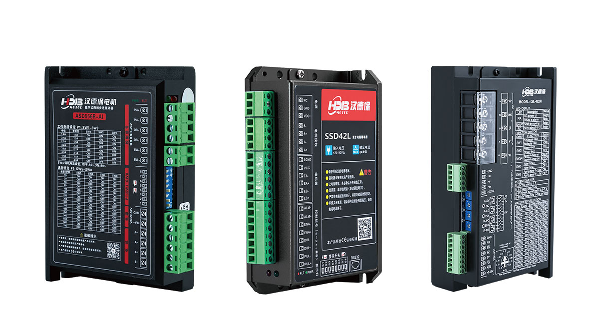
A stepper motor driver is a power and control interface between a motion controller and a stepper motor. Its primary function is to convert low-level step and direction signals from a controller (MCU, PLC, CNC system) into precisely regulated phase currents that drive the motor windings.
Modern HDBMOTOR stepper drivers integrate power electronics, current control, and microstepping logic to ensure smooth, repeatable motion with high torque, making them ideal for 3D printers, CNC machines, robotics, and industrial automation.
How a Stepper Motor Produces Motion
A stepper motor has:
Stator windings (phases)
Rotor with permanent magnets or iron teeth
When a phase is energized, the rotor aligns with the magnetic field. By energizing coils in sequence, the rotor moves in discrete steps rather than continuously, allowing precise positioning. For example, a typical 1.8° stepper motor completes a full rotation in 200 steps.
HDBMOTOR stepper drivers control the sequence and current through these windings, ensuring smooth motion, high torque, and repeatable positioning.
Core Working Principle of a Stepper Motor Driver
A stepper driver operates in three stages:
Receiving Step and Direction Signals
Generating Coil Excitation Sequence
Regulating Phase Current with PWM Control
1. Receiving Step and Direction Signals
Most drivers use a step/direction interface:
Step pulse: Advances the motor by one step or microstep
Direction signal: Defines clockwise or counterclockwise rotation
The controller determines speed (pulse frequency) and position (pulse count). HDBMOTOR drivers are compatible with standard step/direction signals, making integration with MCUs, PLCs, or CNC controllers straightforward.
2. Generating the Phase Excitation Sequence
Inside the driver, step pulses are converted into phase currents:
Bipolar motors: H-bridge circuits drive current in both directions
Unipolar motors: Selectively energize coil segments
Stepping modes supported by HDBMOTOR drivers:
Full-step: Maximum torque, 1.8° steps, more vibration
Half-step: 0.9° steps, smoother motion
Microstepping: High resolution (1/8, 1/16, 1/32 steps), smooth low-speed motion, low acoustic noise
3. Current Regulation and PWM Control
Modern drivers use chopper (PWM) control to regulate phase currents:
Sense resistors monitor current
PWM switches maintain target current
Microstepping shapes sinusoidal or quasi-sinusoidal current profiles
This ensures:
High torque at low speeds
Reduced vibration and resonance
Accurate step positions under variable load
HDBMOTOR microstepping drivers feature adjustable current limits and protection against over-current, over-temperature, and under-voltage.
Practical Benefits and Applications of HDBMOTOR Stepper Drivers
Benefits:
Fine microstepping control for precision motion
High torque and smooth operation
Built-in protection features
Easy integration with controllers via step/direction inputs
Applications:
CNC machines and 3D printers: Precise X-Y-Z positioning
Robotics and industrial automation: Controlled linear and rotary motion
Medical devices and office equipment: Repeatable and reliable motion
Final Notes
A stepper motor driver is not just a power amplifier—it is the precision control system of your motion application. Proper selection of HDBMOTOR stepper drivers ensures:
Smooth and accurate motion
Low vibration and noise
Safe operation under varying loads
If you are unsure about motor sizing, driver selection, or operating margins, you can contact HDBMOTOR engineers for guidance.