
Load Calculations and Tips for Using Step Motors: 7 Essential Guidelines
Understanding load calculations and tips for using step motors is critical for optimizing motor performance and ensuring smooth operation. Step motors are widely used in precision applications, but their effectiveness depends on accurate torque and inertia calculations, speed-torque characteristics, acceleration management, and vibration control. This article provides comprehensive guidance to help you maximize step motor efficiency.
Load Calculations in Step Motors
Accurate load calculations form the basis for selecting and operating step motors effectively. Two primary loads impact motor performance: torque load and inertia load.
Torque Load (Tf)
Torque load is calculated as:
Tf = G × r
G: Weight of the load
r: Radius from the rotation axis to the load
This represents the torque required to turn the load.
Inertia Load (TJ)
Inertia load affects acceleration torque and is computed by:
TJ = J × (dw/dt)
Where:
J = M × (R1² + R2²) / 2 (Kg·cm²)
M: Mass of the rotating part
R1: Outer radius
R2: Inner radius
dw/dt: Angular acceleration
Proper inertia load calculation is essential for determining acceleration torque.
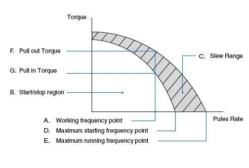
Speed-Torque Characteristics of Step Motors
The dynamic torque curve is crucial to understanding motor performance at varying speeds. Key points include:
Working Frequency Point: Motor speed versus drive pulse rate, calculated by
n = q × Hz / (360 × D), where q is step angle, Hz pulse frequency, and D subdivision value.Start/Stop Region: Speeds where the motor can start or stop directly.
Slew Range: The motor must accelerate through this region; direct start or stop here causes lost steps.
Maximum Starting and Running Frequency Points: Highest speeds achievable under no load.
Pull-in and Pull-out Torque: Maximum torque the motor can handle when starting and running respectively.
Understanding these characteristics helps prevent step loss and ensures smooth operation.
Calculating Acceleration Torque
Acceleration torque often exceeds load friction and limits acceleration speed.
Straight-Line Acceleration
Typically, TJ is about 70% of the maximum motor torque (Tm).
Acceleration time tr is:
tr = 1.8 × 10⁻⁵ × J × q × (F1 - F0) / (TJ - TL)Torque during acceleration varies linearly:
F(t) = (F1 - F0) × t / tr + F0
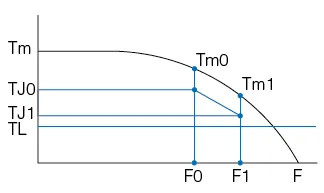
Exponential Acceleration
Uses inertia estimates with:
TJ0 = 70% Tm0, TJ1 = 70% Tm1, TL = 60% Tm1Acceleration time:
tr = F4 × ln[(TJ0 - TL) / (TJ1 - TL)]Torque over time:
F(t) = F2 × [1 – e^(–t/F4)] + F0
Constants F2 and F4 depend on motor and load.
Tips for Reducing Vibration and Noise in Step Motors
Vibration and noise often occur near resonant frequencies. To minimize:
Operate Outside Resonant Speed Ranges.
Use Micro-stepping: Divides steps for smoother motion, reducing vibration and noise. Note torque decreases by ~15% in half-step and ~30% with sine-wave current control.
Choose Specialized Motors: 0.9° two-phase or three-phase step motors reduce vibration and improve smoothness.
Conclusion
Mastering load calculations and tips for using step motors ensures reliable and efficient motor performance. From torque and inertia computations to speed-torque understanding and vibration control, applying these tips will help optimize your step motor applications.
Recommended Articles:
Stepper Motor Step Angle and Calculation Formula: Complete Guide (2025)
Difference Between Sinking Current and Sourcing Current: 7 Powerful Facts
Motor Torque Calculation Formula: Simple Guide with 5 Key Torque Formulas